ControlWave Instruction Manual (CI-ControlWave)
2-28 Installation Revised Nov-2010
Pin
RS-485
Signal
RS-485 Description
3 RXD- Receive Data – Input
4
5 TXD- Transmit Data – Output
6
7 TXD+ Transmit Data + Output
8 ISOGND Isolated Ground
Table 2-11. RS-485 COM4 Port (Male DB9) Connector Pin Assignment
Pin
RS-485
Signal
RS-485 Description
1
2 RXD- Receive Data - Input
3 TXD- Transmit Data - Output
4 TXD+ Transmit Data + Output
5 ISOGND Isolated Ground
6 RXD+ Receive Data + Input
7
8
9
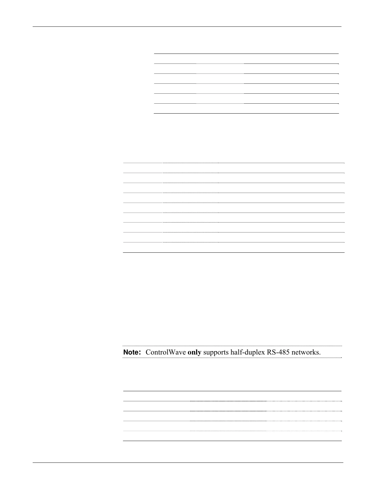
Since the RS-485 port is intended for network communications, refer to
Table 2-12 for the appropriate connections for wiring the master, first
slave, and nth slave.
Essentially, the master and the first slave transmit and receive data on
opposite lines; all slaves (from the first to the nth) are paralleled (daisy-
chained) across the same lines. Wire the master node to one end of the
RS-485 cable run using a 24-gauge paired conductor cable (such as a
Belden 9843).
Note: ControlWave only supports half-duplex RS-485 networks.
Table 2-12. RS-485 Network Connections
From Master To First Slave To nth Slave
TXD+ RXD+ RXD+
TXD– RXD– RXD–
RXD+ TXD+ TXD+
RXD– TXD– TXD–
ISOGND ISOGND ISOGND

 Loading...


