ER5000 —
103
Installation Variations
Feedback Wiring Variations
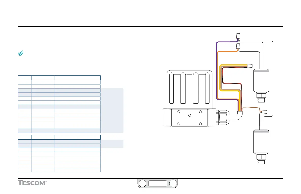
Switch Feedback Control to a Second Feedback Source
NOTENOTE
CAUTIONCAUTION
WARNINGWARNING
This feature is only available on “F” models of the ER5000.
In “F” model ER5000s, the feedback source can easily be switched
between two feedback sources. Refer to Table 22 for correct wiring.
Table 22: Wiring For Two Feedback Sources (Two Wire Transducer)
J3 Pins Wire Color Function
1 brown +setpoint input
2 red -setpoint input
3 orange +feedback input
4 yellow -feedback input
5 green -RS485 network connection
6 blue +RS485 network connection
7 violet +24V DC power
8 gray 24V return (power ground)
9 white +5V output (5 mA max.)
10 black analog signal/board ground
*11 *pink analog signal output
(active in Enhanced “F” models ONLY)
12 tan analog signal/board ground
J4 Pins Wire Color Function
1 brown/white +aux input #1
2 red/black -aux input #1
3 orange/black +aux input #2
4 yellow/black -aux input #2
5 green/white suspend control
6 black/white digital output/board ground
7 blue/white digital output #1
8 gray/black digital output #2
(continued next page)
TRANSDUCER
#2
TRANSDUCER
#1
YELLOW
ORANGE
VIOLET
RED/BLACK
TAN
BROWN/WHITE
+ OUTPUT + OUTPUT
+ SUPPLY
+ SUPPLY
Figure 39: Switch Between Two External Feedback Sources
 Loading...


