ER5000 —
90
Installation Variations
Setpoint Wiring Variations
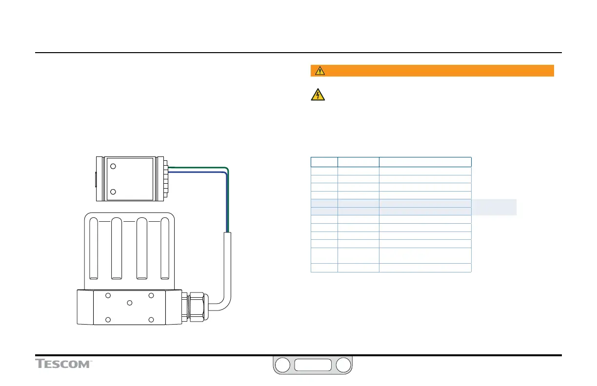
Digital Setpoint Source — RS485 Connection,
USB to RS485 Converter (TESCOM™ Model #82948)
For most applications, the supplied USB cable provides the most
efcient connection to the PC. The controller can also be wired to
connect through an RS485 converter, as shown in Figure 28.
TDB(+)
TDA(
-
)
GREEN
BLUE
Figure 28: RS485 Connection (USB to RS485 Converter)
WARNING
The controller must be disconnected from the power supply before
any additional wiring or change to jumper configuration is
performed. Do not reconnect the power supply until all additional
wiring connections have been made and are properly installed.
Refer to Table 11 to verify correct wiring.
Table 11: Wiring for RS485 Connection (USB to RS485 Converter)
J3 Pins Wire Color Function
1 brown +setpoint input
2 red -setpoint input
3 orange +feedback input
4 yellow -feedback input
5 green -RS485 network connection
6 blue +RS485 network connection
7 violet +24V DC power
8 gray 24V return (power ground)
9 white +5V output (5 mA max.)
10 black analog signal/board ground
*11 *pink analog signal output
(active in Enhanced “F” models ONLY)
12 tan analog signal/board ground
The USB to RS485 converter is powered through its USB
connection, so it does not require direct wiring to a power supply.
 Loading...


