EasyManua.ls Logo

Emerson Tescom ER5050 User Manual

Emerson Tescom ER5050
248 pages
To Next Page IconTo Next Page
To Previous Page IconTo Previous Page
Page #217 background imageLoading...
Page #217 background image
ER5000
217
Troubleshooting
Using Profiles to Control the ER5000
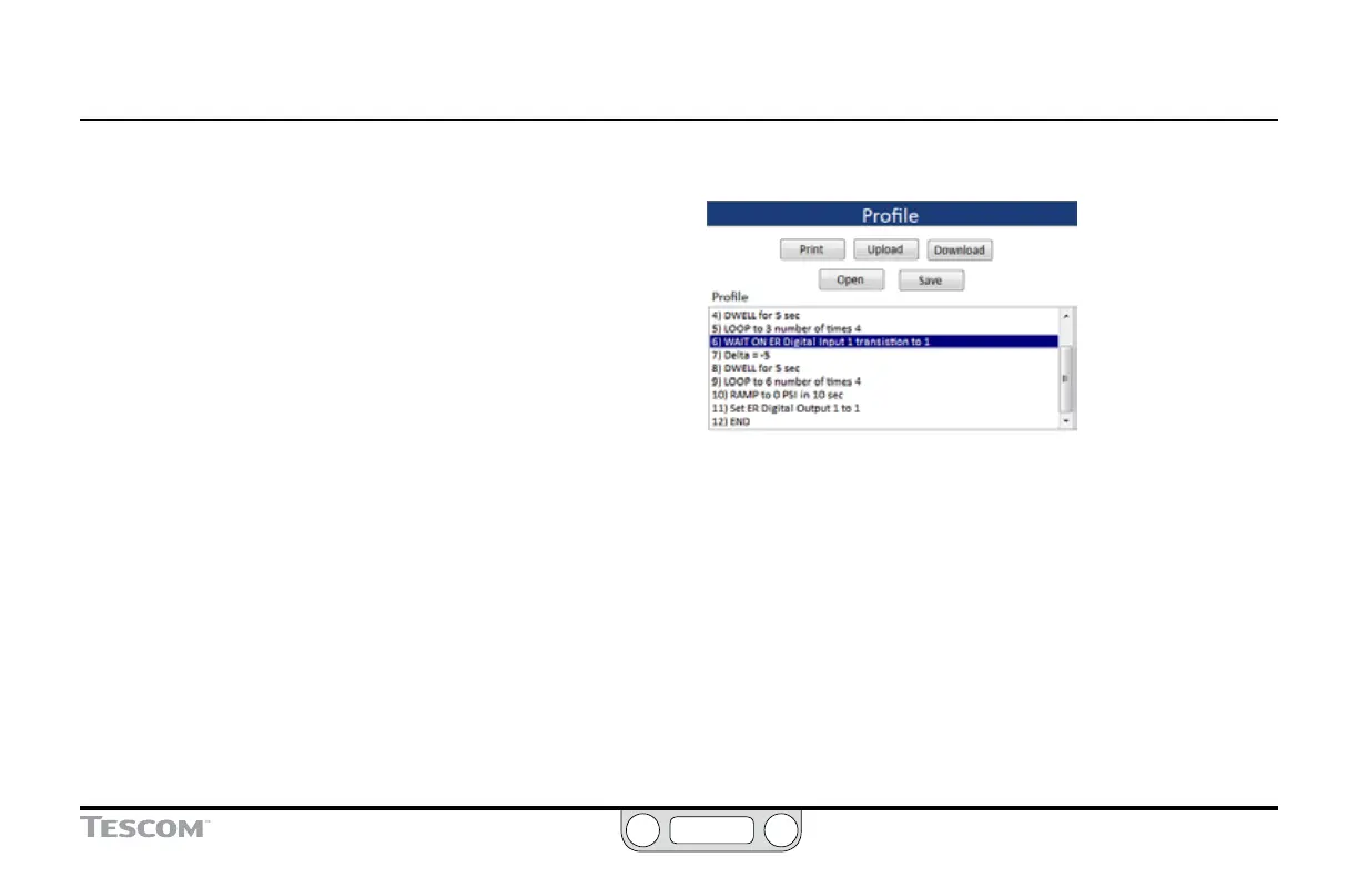
Proles are multi-step command sequences for the ER5000. They
require no previous programming experience on the part of the
user to create and guide the ER5000 through everything from a
simple start/stop operation to a sequence of setpoint changes
that can include up to one hundred command lines and control
loops that can run indenitely.
Problems with Proles can generally be attributed to applications
where a Prole includes command segments where the controller
communicates with an external digital device. Troubleshooting
these applications generally involves checking that all wiring is
congured properly and correctly setting the internal variables
which control how the ER5000 interprets digital signals.
Input – If the Profile Stops at a Digital Input Command for
Digital Input 1
1. Check Jumper J14. It must be OFF to use Input 1 as a digital
input. Refer to Checking the Conguration of the Jumpers
earlier in this section.
2. Check variable #77 ( ID_COMPENSATED_EXTRA_AD1).
The value should read higher when the input is activated
(Logical 1) than when not activated (Logical 0).
3. Use one of the extra variables on the plot screen to monitor
Extra Analog Input 1 (77). Follow the steps in To add a variable to
the Plot Screen display.
OR
Use a Read/Write eld in The Read/Write Panel to monitor
77:COMP_EXTRA–AD1.
(continued next page)

Table of Contents

Question and Answer IconNeed help?

Do you have a question about the Emerson Tescom ER5050 and is the answer not in the manual?

Emerson Tescom ER5050 Specifications

General IconGeneral
ModelER5050
TypeElectronic Pressure Controller
Power Supply24 VDC
Supply Voltage24 VDC ±10%
Communication ProtocolRS-485 Modbus RTU
CommunicationRS-485 Modbus RTU
Output Signal4-20 mA
Wetted Materials316L Stainless Steel

Summary

Safety, Installation & Operations Precautions

Features and Specifications

ER5000 Specifications

Details the technical specifications for the ER5000, including enclosure, weight, media, and environment.

Hazardous Location Model (ER5050) Specifications

Outlines the specific specifications for the ER5050 Hazardous Location model.

How It Works

The ER5000: How It Works

Explains the ER5000's function as a microprocessor-based PID controller for pressure control applications.

Tuning a PID Controller

Details the process of selecting optimal PID settings (Kp, Ki, Kd) for controller performance.

Typical Application

The ER5000: Typical Application (Non-Hazardous Location)

Describes a typical application for controlling system pressure using the ER5000 with an air-actuated regulator.

Control Modes

Getting Started

Verify the configuration of your application

Guidance on verifying the application's configuration, including components and connections for typical setup.

Verify that all operational requirements have been met

Checklists for ensuring supply pressure, filters, lines, and fittings meet operational requirements.

Verify that all safety requirements have been met

Confirmation of understanding all safety warnings and cautions before operation.

Mount the ER5000 on the regulator

Step-by-step instructions for mounting the ER5000 controller onto the regulator.

Connect and verify the power supply

Procedures for connecting and verifying the 24V DC power supply to the ER5000 controller.

Connect the transducer wiring to provide a feedback signal

Wiring instructions for connecting the transducer to provide a feedback signal to the ER5000.

Install the ERTune™ program

Guide on downloading, installing, and setting up the ERTune™ software for controller configuration.

Connect pressure to the system

Steps for connecting the inlet pressure source and understanding output pressure connections.

Start up and tune the system

Final steps for system startup, connecting regulator pressure, and optimizing performance with ERTune™.

Installation Variations

ER5000 Installation Variations — Wiring Diagrams

Overview of wiring options for configuring the ER5000 for various application requirements.

Power Supply Wiring — All Applications

Details on wiring all ER5000 models to a 24V DC power supply, regardless of configuration.

Installing a Hazardous Location Model (ER5050)

Specific instructions and warnings for installing the ER5050 in hazardous locations per codes.

The ERTune™ Program

The ERTune™ Program: Basic Features

Overview of the ERTune™ program's capabilities for setup, tuning, and monitoring the ER5000.

Installing the ERTune™ Program

Step-by-step guide for installing the ERTune™ software and its components.

To open the ERTune™ program

Instructions on how to launch the ERTune™ program, including troubleshooting for communication errors.

Troubleshooting

Internal Variables

Certifications and Warranty

Related product manuals