ER5000 —
83
Installation Variations
Setpoint Wiring Variations
Analog Setpoint Source — Potentiometer
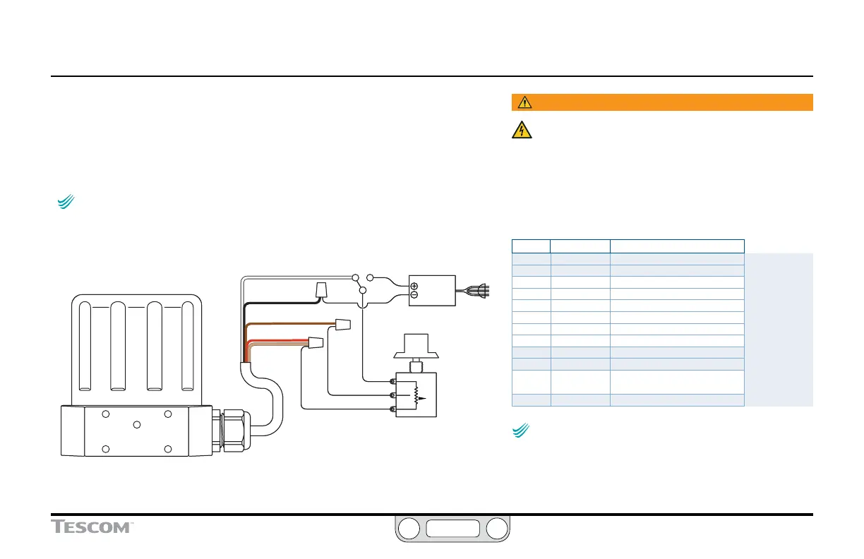
Figure 22 shows correct wiring to provide a 0–5V signal to the
analog setpoint from a potentiometer.
NOTENOTE
CAUTIONCAUTION
WARNINGWARNING
The 0–1V range can be programmed as a Control Limit for
1–5V ER5000s. Refer to The Control Limits Panel for more information on
this feature.
BLACK
RED
WHITE
+5 +10
POWER SUPPLY
10V DC
120V AC
BROWN
TAN
10K
HIGH
WIPER
LOW
Figure 22: Potentiometer Analog Setpoint
WARNING
The controller must be disconnected from the power
supply before any additional wiring or change to
jumper configuration is performed. Do not reconnect
the power supply until all additional wiring connections
have been made and are properly installed.
Refer to Table 5 to verify correct wiring.
Table 5: Wiring for Potentiometer Analog Setpoint
J3 Pins Wire Color Function
1 brown +setpoint input
2 red -setpoint input
3 orange +feedback input
4 yellow -feedback input
5 green -RS485 network connection
6 blue +RS485 network connection
7 violet +24V DC power
8 gray 24V return (power ground)
9 white +5V output (5 mA max.)
10 black analog signal/board ground
*11 *pink analog signal output
(active in Enhanced “F” models ONLY)
12 tan analog signal/board ground
NOTENOTE
CAUTIONCAUTION
WARNINGWARNING
The ER5000 cannot directly provide a 0–10V signal.
An external 10V supply must be used.
 Loading...


