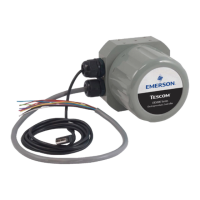
ER5000 —
27
What’s New
Replacing an ER3000 with an ER5000
IMPORTANT
IMPORTANT
Reference current Hazardous Location
standards when replacing a Hazardous Location
ER3000 with an ER5050.
WARNING
Safety standards are subject to continual revision. Investigate and apply
the most recent standards for Hazardous Locations for your area set by
ANSI, ISO and OSHA, as well as all electrical codes and fire and safety
standards, before replacing a controller in a hazardous location.
Click this link to view all Hazardous Location certifications and
specifications.
Wiring for the Standard Model ER5000
The wiring for the 12-pin MTA connector is the same for the
ER5000SI-1 as it was for the ER3000SI-1. An MTA connector
replacement kit is available to allow use of the existing installation
cable with the new ER5000.
Wiring for the “F” Model ER5000
For “F” model ER5000s, the 12-pin MTA connector and 8-pin
auxiliary MTA connector, which were previously fed by separate
cables, are now fed by a single 20-wire cable. All wires feeding the
8-pin connector are color striped to distinguish them visually from
the solid color wires feeding the 12-pin connector. Refer to
Figure 18 to see all wire colors and pin terminations.
The function of the green/white wire (J4 Pin 5), which was
previously the Analog Signal Ground, has changed: it now
activates the Suspend Control function, which closes both valves
and locks the controller at the current pressure. If your current
application makes use of this wire, refer to the Installation
Variations section for recommended wiring congurations.
For standard model ER5000s, there are two wires which act
as signal/board grounds: the black wire (J3 Pin 10) and the tan
wire (J3 Pin 12).
For “F” model ER5000s, the black/white wire (J4 Pin 6) also acts as
signal/board ground.

 Loading...


