ER5000 —
81
Installation Variations
The recommended conguration for the Ground Filter
Bypass jumper (J1) is not installed (OFF). Installing this jumper
connects signal ground directly to the power supply ground.
This conguration is rarely used and should only be considered
when there is an extreme level of operational noise. Refer to the
Troubleshooting section before installing this jumper.
LED Indicators
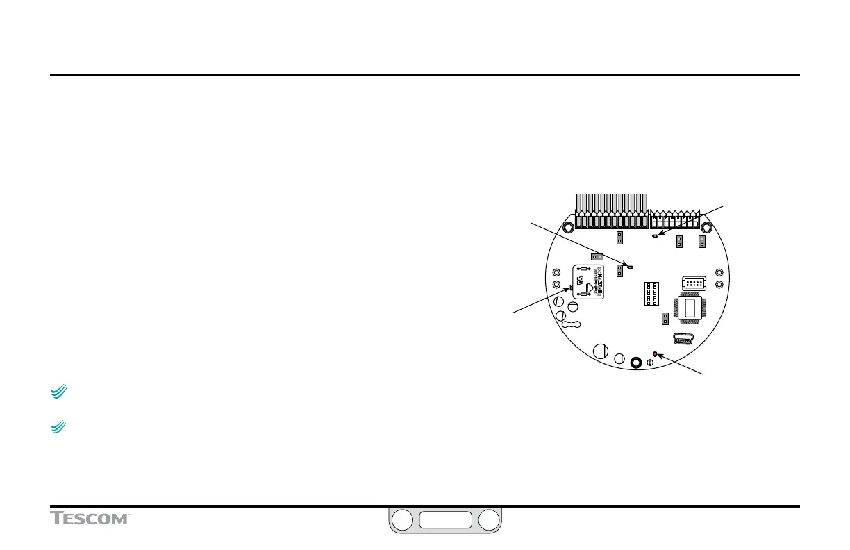
Figure 20 shows the position of the four LED indicators on the
circuit board of the ER5000. The LED indicators give you a quick
visual reference to evaluate the status of the controller.
During installation, use LED1 (red) and LED4 (red) to verify that
you have correctly wired the ER5000 to its power supply.
If you are communicating via RS485, for example as part of a
daisychain on a network, LED2 (green) and LED3 (amber) verify
that the ER5000 is sending and receiving data.
NOTENOTE
CAUTIONCAUTION
WARNINGWARNING
Refer to page 89 through page 93 for correct wiring to
connect the ER5000 to an RS485 converter.
NOTENOTE
CAUTIONCAUTION
WARNINGWARNING
LED2 and LED3 respond to data transmission when the
ER5000 communicates using RS485. These LEDs do not respond to data
transmission when the ER5000 communicates using USB and may be on or
off depending on the specic conguration of your application. They do not
need to be checked during installation or operation when USB is used.
The LEDs can help you troubleshoot controllers that are not
functioning properly. For further information, refer to the
Troubleshooting section.
LED4
“Heartbeat”
(red)
should blink on and off at
a steady rate
LED1
Power Indicator
(red)
should be on
continuously
LED3
Receiving Data
(amber)
blinks when ER5000
is receiving data in via
RS485
LED2
Sending Data
(green)
blinks when ER5000
is sending data
out via RS485
Figure 20: LED Indicators
 Loading...


