ER5000 —
107
Installation Variations
Wiring Variations for Additional Functions
Digital Outputs
NOTENOTE
CAUTIONCAUTION
WARNINGWARNING
This feature is only available on “F” models of the ER5000.
The ER5000 can provide digital outputs to the rest of the system.
Refer to Table 25 for correct wiring.
Table 25: Wiring for Digital Outputs
J3 Pins Wire Color Function
1 brown +setpoint input
2 red -setpoint input
3 orange +feedback input
4 yellow -feedback input
5 green -RS485 network connection
6 blue +RS485 network connection
7 violet +24V DC power
8 gray 24V return (power ground)
9 white +5V output (5 mA max.)
10 black analog signal/board ground
*11 *pink analog signal output
(active in Enhanced “F” models ONLY)
12 tan analog signal/board ground
J4 Pins Wire Color Function
1 brown/white +aux input #1
2 red/black -aux input #1
3 orange/black +aux input #2
4 yellow/black -aux input #2
5 green/white suspend control
6 black/white digital output/board ground
7 blue/white digital output #1
8 gray/black digital output #2
(continued next page)
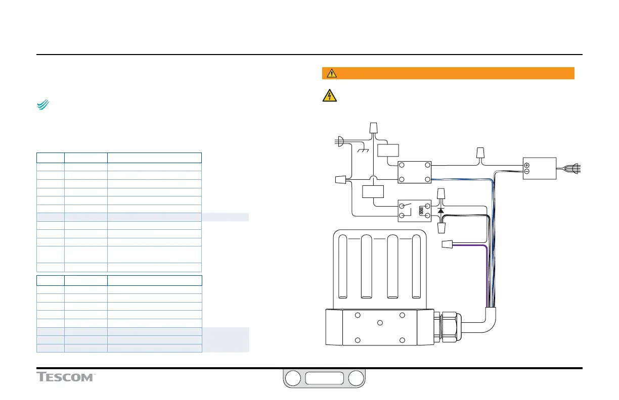
WARNING
The controller must be disconnected from the power supply before
any additional wiring or change to jumper configuration is
performed. Do not reconnect the power supply until all additional
wiring connections have been made and are properly installed.
BLACK/WHITE
LOAD 2
LOAD 1
GRAY/BLACK
BLUE/WHITE
POWER SUPPLY
12V DC
120V AC
SOLID STATE
RELAY
MECHANICAL
RELAY
VIOLET
Figure 42: ER5000 Digital Outputs
 Loading...


