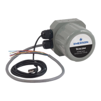
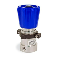
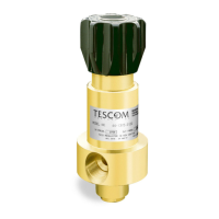
ER5000 —
31
How It Works
Understanding PID Controllers
PID Controllers allow mechanical systems to operate at a high
level of precision and dependability with only occasional oversight
by human operators. They can control virtually any measurable
physical property within the system, including pressure, ow,
temperature, position, speed, force, consistency, torque
and acceleration.
PID controllers operate in a continuous loop of monitoring and
response. The ER5000 performs one loop every 25 ms (milliseconds).
At the start of each loop, the controller reads the input from a sensor
within the system to nd the current level of a measured property
such as system pressure (the Feedback) and compares it to a preset
target value (the Setpoint).
If the two values match, a Zero Error is generated and no action is
taken. If the two values do not match, a positive or negative Error is
generated and the controller activates to correct the error.
When the error is the result of an unintended change in the
operating environment, the controller works to return the system
to its previous level. When the error is the result of a scheduled
change in the setpoint, the controller works to raise or lower the
system to the new target level.
In either case, the controller continues to act until setpoint and
feedback are equal. The controller then generates a zero error and
returns to its monitoring function. At this point, the system is said
to be in a Stable State.
The response of the PID controller, from error generation to
stable state, is shaped by a complex algorithm that incorporates
three independent but interrelated values (also referred to
as Terms).
• The Proportional (P) term is a function of the value of the
error generated during the current loop. With each loop,
the P value changes in direct proportion to the amount of
error. Proportional is largest when the error is rst detected
and grows progressively smaller as the controller brings the
system closer to setpoint.
• The Integral (I) term is a function of the combined values
of all errors generated while the system is in operation. The
I value continues to increase as long as the system is in error
and will only decrease when an error is recorded in the opposite

 Loading...


