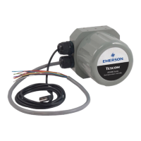
ER5000 —
11
Table of Contents
Voltage/Current Select Jumpers . . . . . . . 80
LED Indicators . . . . . . . . . . . . . . . . 81
Power Supply Wiring — All Applications . . . 82
Setpoint Wiring Variations . . . . . . . . . . 83
Analog Setpoint Source — Potentiometer 83
Analog Setpoint Source — Current/Voltage 84
Analog Setpoint Source —
Passive PC or PLC D/A Card 85
Analog Setpoint Source —
Active PC or PLC D/A Card 86
Prole with External Control/Digital Inputs 87
Digital Setpoint Source — RS485 Connection,
RS232 to RS485 Converter
(TESCOM™ Model #85061) 89
Digital Setpoint Source — RS485 Connection,
USB to RS485 Converter
(TESCOM Model #82948) 90
Digital Setpoint Source — RS485 Network,
RS232 to RS485 Converter
(TESCOM Model #85061) 91
Digital Setpoint Source — RS485 Network,
USB to RS485 Converter
(TESCOM Model #82948) 93
Feedback Wiring Variations . . . . . . . . . . 95
Two Wire Transducer 95
Three Wire Transducer 96
Four Wire Transducer 97
4–20 mA External Feedback, Floating Input,
Feedback Signal Monitored by PC or PLC A/D Card 98
4–20 mA External Feedback, Ground
Referenced Input, Feedback Signal Monitored
by PC or PLC A/D Card 99
Two Wire Transducer, PC or PLC A/D Card
Used to Monitor Voltage Produced by the
4–20 mA External Feedback 100
Three Wire Transducer, PC or PLC A/D Card
Used to Monitor Voltage Produced by the
4–20 mA External Feedback 101
Four
Wire Transducer, PC or PLC A/D Card Used
to Monitor Voltage Produced by the 4–20 mA
External Feedback 102
Switch Feedback Control to a Second
Feedback Source 103
Wiring Variations for
Additional Functions . . . . . . . . . . . . . 104
Monitoring Additional Analog Inputs 104
Monitoring the ER5000’s Internal Sensor
Using the Analog Output, 4–20 mA Wiring 105
Monitoring the ER5000’s Internal Sensor
Using the Analog Output, 0–10V Wiring 106
Digital Outputs 107
Suspend Mode 109
Installing a Hazardous Location
Model (ER5050) . . . . . . . . . . . . . . . 110
The ERTune
™
Program 111
ER5000 Software
Development Support 196
ER5000 Communication Requirements . . . . 197
ER5000 Software Development Support . . .197
Windows Programming Examples . . . . . .198
Accessing the Windows DLL File . . . . . . .199
The TESCOM Protocol . . . . . . . . . . . . . 200
Troubleshooting 202
Installation . . . . . . . . . . . . . . . . . . 203
Operation . . . . . . . . . . . . . . . . . . 206
RS485 Communication . . . . . . . . . . . . 216
Using Profiles to Control the ER5000 . . . . . 217
Internal Variables 221
Table of ER5000 Internal Variables . . . . . . 222
ER5000 Internal Variables . . . . . . . . . . 225
ER5000 Setpoint and Feedback Variables 225
ER5000 Conguration Variables 226
ER5000 Inner Loop Tuning Variables 227
ER5000 Outer Loop Tuning Variables 228
ER5000 Analog Input Variables 229
ER5000 Pressure Prole Variables 230

 Loading...


