Home
Emerson
Controller
Tescom ER5050
Emerson Tescom ER5050 User Manual
4
of 1
of 1 rating
248 pages
Give review
Manual
Specs
To Next Page
To Next Page
To Previous Page
To Previous Page
Loading...
ER5000
—
247
Setting up the ER
T
une™ Program on Windows 8 PCs
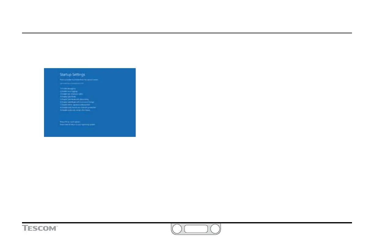
8.
After the ope
rating system h
as reboo
ted, the
Startup Settings
window appe
ars. Press the F7 key t
o disable the Driver
Signatur
e Enforce
ment f
eature
.
9.
Windo
ws 8 will restar
t. The Driver Signa
ture Enforc
emen
t
will be disabled until the next reboo
t.
246
248
Table of Contents
Default Chapter
3
Tescom™ Electronic Controllers
3
Tescom Regulators
6
Table of Contents
9
Table of Contents
10
Conventions of this Manual
13
Navigating this Manual
13
Features and Specifications
14
ER5000 Series Part Numbering System
15
ER5000 Standard Features
15
ER5000 Dimensions - Side Views
16
ER5000 Dimensions - Top and Bottom View
17
ER5050 Hazardous Location Model
18
Dimensions - Side Views
18
ER5050 Hazardous Location Model
19
Dimensions - Top and Bottom View
19
ER5000 Specifications
20
Hazardous Location Model (ER5050) Specifications
22
Accessories
24
What's New
25
New Features
26
Replacing an ER3000 with an ER5000
27
How It Works
29
The ER5000: How It Works
30
Understanding PID Controllers
31
PID Controllers: Three Components Are Better than One
32
A Typical PID Control System
33
Tuning a PID Controller
35
Rules of Thumb for PID Tuning
35
The ER5000: Typical Application (Non-Hazardous Location)
39
Controlling System Pressure
39
A Note Concerning Non-Venting Regulators in Closed Loop Applications
41
Monitoring System Control Limits
42
The ER5000: Control Modes
43
Internal Feedback Mode
43
External Feedback Mode
43
Cascade Mode
43
Glossary of Terms
44
Terms Relating to PID Controllers and Controller Tuning
45
Terms Relating to Regulators
52
Getting Started
57
Before You Begin
58
ER5000 Quick Reference: Jumpers, Terminal Blocks and Wires and Leds
59
Verify Your Shipment
60
Additional Items Not Included
61
Tools You will Need for the Installation
61
Additional Items and Tool You will Need for an Installation in a Hazardous Location
61
Verify the Configuration of Your Application
62
Verify that All Operational Requirements Have Been Met
63
Verify that All Safety Requirements Have Been Met
63
Mount the ER5000 on the Regulator
64
Connect and Verify the Power Supply
65
Verify the Jumper J6 Configuration
68
Connect the USB Cable (Not Supplied with ER5050)
71
Install the Ertune™ Program
72
Connect Pressure to the System
73
Start up and Tune the System
75
Installation Variations
76
Before You Begin
77
ER5000 Installation Variations - Wiring Diagrams
78
Terminal Blocks and Wires
79
Voltage/Current Select Jumpers
80
LED Indicators
81
Power Supply Wiring - All Applications
82
Analog Setpoint Source - Potentiometer
83
Analog Setpoint Source - Current/Voltage
84
Analog Setpoint Source - Passive PC or PLC D/A Card
85
Analog Setpoint Source - Active PC or PLC D/A Card
86
Profile with External Control/Digital Inputs
87
Digital Setpoint Source - RS485 Connection, RS232 to RS485 Converter (TESCOM™ Model #85061)
89
Digital Setpoint Source - RS485 Connection, USB to RS485 Converter (TESCOM Model #82948)
90
Digital Setpoint Source - RS485 Network
91
(TESCOM Model #85061)
91
Digital Setpoint Source - RS485 Network, USB to RS485 Converter (TESCOM Model #82948)
93
Feedback Wiring Variations
95
Two Wire Transducer
95
Three Wire Transducer
96
Four Wire Transducer
97
Ma External Feedback, Floating Input, Feedback Signal Monitored by PC or PLC A/D Card
98
Ma External Feedback, Ground Referenced Input, Feedback Signal Monitored by PC or PLC A/D Card
99
Two Wire Transducer, PC or PLC A/D Card Used to Monitor Voltage Produced by the 4-20 Ma External Feedback
100
Three Wire Transducer, PC or PLC A/D Card Used to Monitor Voltage Produced by the 4-20 Ma External Feedback
101
Four Wire Transducer, PC or PLC A/D Card Used to Monitor Voltage Produced by the 4-20 Ma External Feedback
102
Switch Feedback Control to a Second Feedback Source
103
Wiring Variations for Additional Functions
104
Monitoring Additional Analog Inputs
104
Monitoring the Er5000'S Internal Sensor Using the Analog Output, 4-20 Ma Wiring
105
Monitoring the Er5000'S Internal Sensor Using the Analog Output, 0-10V Wiring
106
Digital Outputs
107
Suspend Mode
109
Installing a Hazardous Location Model (ER5050)
110
The Ertune Program
111
Development Support 196
197
ER5000 Software Development Support
197
ER5000 Communication Requirements
197
Windows Programming Examples
198
Accessing the Windows DLL File
199
The TESCOM Protocol
200
Troubleshooting
202
Installation
203
Operation
206
RS485 Communication
216
Using Profiles to Control the ER5000
217
Internal Variables
221
Table of ER5000 Internal Variables
222
ER5000 Internal Variables
225
ER5000 Configuration Variables
226
ER5000 Inner Loop Tuning Variables
227
ER5000 Outer Loop Tuning Variables
228
ER5000 Analog Input Variables
229
ER5000 Pressure Profile Variables
230
Control Variable
231
ER5000 Analog and Digital Output Variables
232
ER5000 Pulse Width Modulation (PWM Control Variables
233
ER5000 Gain/Offset Variables
234
ER5000 Control Limit Variables
235
Certifications and Warranty
237
Hazardous Locations Special Requirements and Certifications for the ER5050
238
Limited Warranty
240
Ertune ™ Program on Windows 8 Pcs
242
Windows 8 Pcs
244
Ertu N Eprogram on
244
Appendix A: Set Ting up the
244
Installing the ER5000 Device Driver
244
4
Based on 1 rating
Ask a question
Give review
Questions and Answers:
Need help?
Do you have a question about the Emerson Tescom ER5050 and is the answer not in the manual?
Ask a question
Emerson Tescom ER5050 Specifications
General
Brand
Emerson
Model
Tescom ER5050
Category
Controller
Language
English
Related product manuals
Emerson Tescom ER5000 Series
248 pages
Emerson TESCOM 04 Series
23 pages
Emerson TESCOM 54-2000 Series
23 pages
Emerson TESCOM 26-1700 Series
23 pages
Emerson TESCOM 26-2000 Series
23 pages
Emerson TESCOM 26-1200 Series
23 pages
Emerson TESCOM 44-1300 Series
23 pages
Emerson TESCOM 44-5200 Series
23 pages
Emerson Tescom 26-1000 Series
23 pages
Emerson TESCOM 44-1100 Series
23 pages
Emerson TESCOM 44-2200 Series
23 pages
Emerson TESCOM 26-1600 Series
23 pages
 Loading...


