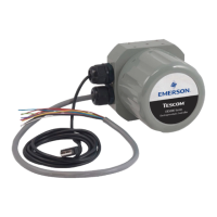
ER5000 —
88
Installation Variations
Profile with External Control/Digital Inputs (cont.)
Additionally, the Digital Input push button can be used if the
“Digital Input” function has been used within the Prole. This allows
an operator the exibility to wait until an event has occurred, such
as changing to the next device.
When Auxiliary Input #2 (orange/black wire, J4 Pin 3) is used as the
Prole Start/Stop signal and Auxiliary Input #1 (brown/white wire,
J4 Pin 1) is used as the Digital Input signal, the ER5000 allows you
to adjust the toggle level (also referred to as the trip point) of the
input. This is the level where the analog input switches between a
logical 0 and a logical 1.
For example, when a pressure transducer is connected to the
Digital Input, this feature allows the ER5000 to wait for a specic
pressure before continuing on in the Prole.
The ER5000 toggle variables enable this feature. Refer to the
ER5000 Analog Input Variables section for more information.

 Loading...


