ER5000 —
92
Installation Variations
Digital Setpoint Source — RS485 Network,
RS232 to RS485 Converter (TESCOM™ Model #85061) (cont.)
Each ER5000 in the network must be assigned a unique Node
Address. All ER5000s are assigned a default Node Address of 250;
therefore, the addresses must be changed to allow them to all
communicate on the network.
The Node Address can be changed as part of the setup procedure
or at any time afterwards using The Congure Tab.
Refer to To set up the ERTune™ program to work with the ER5000
and The Congure Tab for more information on how to modify the
Node Address of the ER5000 using the ERTune™ program.
Repeat this process for each ER5000 in the network. Be sure to
give each controller a unique Node Address within the network.
You may leave one ER5000 at the default value.
NOTENOTE
CAUTIONCAUTION
WARNINGWARNING
The number you assign should be lower than 250. Numbers
higher than 250 will be truncated to the rst two digits.
NOTENOTE
CAUTIONCAUTION
WARNINGWARNING
The power supply for your network must be able to provide
300 mA to each ER5000 in the daisychain.
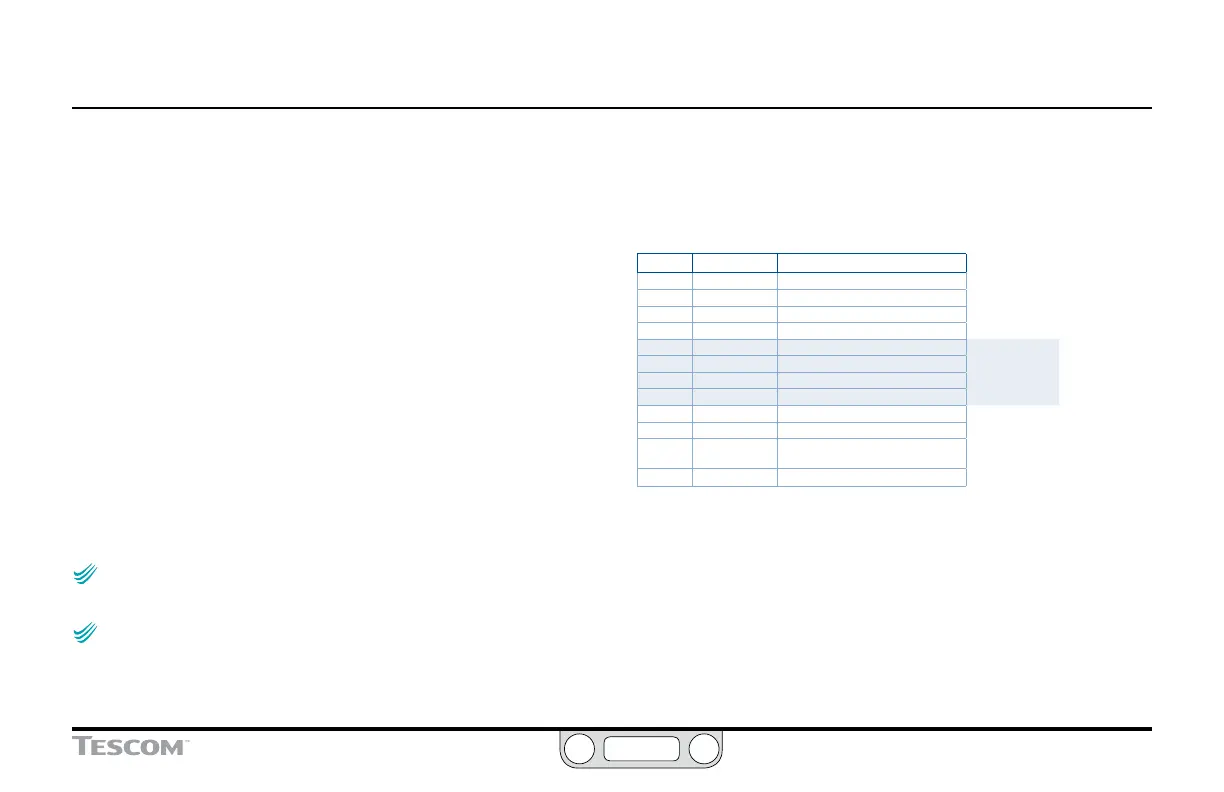
Refer to Table 12 to verify correct wiring.
Table 12: Wiring for Networked Connection (RS232 to RS485 Converter)
J3 Pins Wire Color Function
1 brown +setpoint input
2 red -setpoint input
3 orange +feedback input
4 yellow -feedback input
5 green -RS485 network connection
6 blue +RS485 network connection
7 violet +24V DC power
8 gray 24V return (power ground)
9 white +5V output (5 mA max.)
10 black analog signal/board ground
*11 *pink analog signal output
(active in Enhanced “F” models ONLY)
12 tan analog signal/board ground
The RS232 to RS485 converter requires direct wiring to an
external power supply, so it must be connected to the ER5000’s
power supply wiring. The violet wire (Pin 7) connects to the
+24V DC terminal and the gray wire (Pin 8) connects to the
ground terminal.
 Loading...


