SE Group Confidential (Related Staff Only)
Disassembly/Reassembly Overview 12
SC-P600 Revision D
1.1.4 Preparation before Returning the Unit to the User
When returning the printer to the user, make sure to secure the specified points with tapes to avoid damaging the
printer during transport.
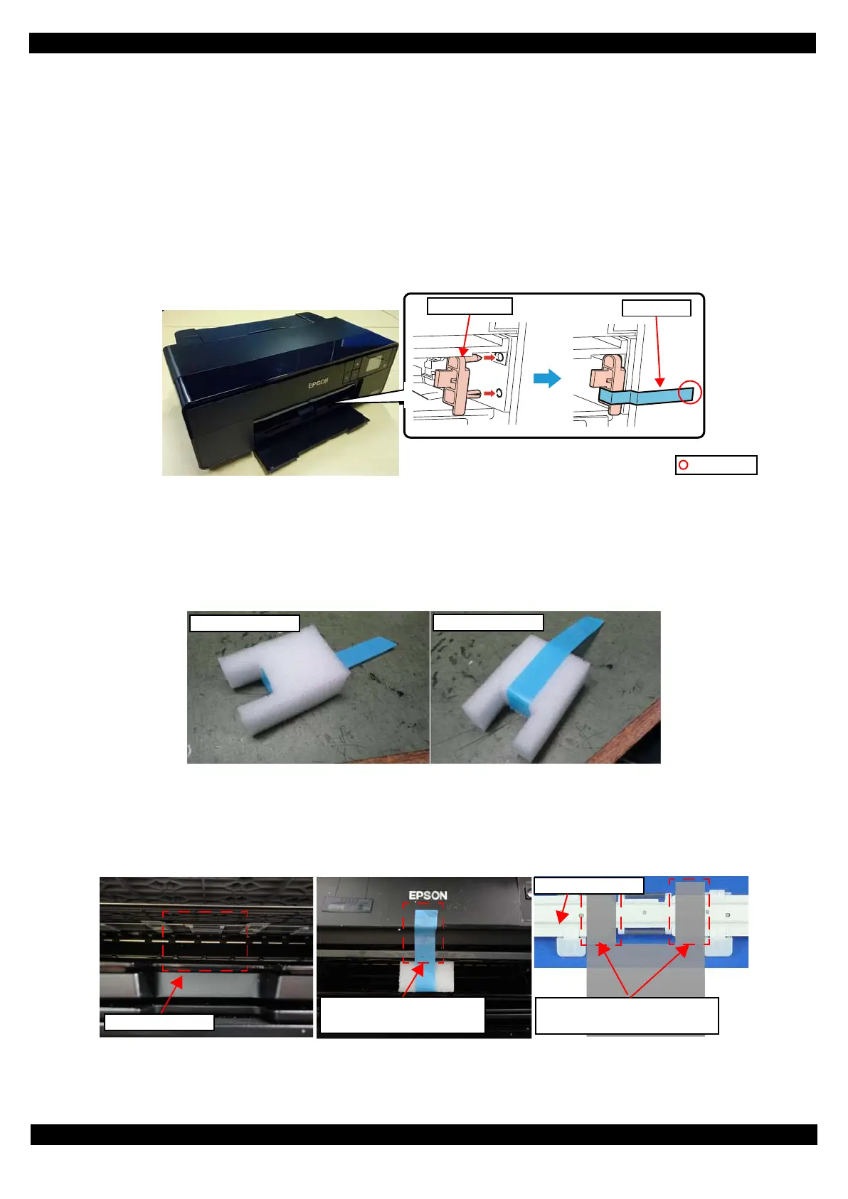
Attaching the front tray lock (tape length: 90
±
2 mm, tape width: 18 mm, fold one end by 5 mm)
Attach the front tray lock (1535369) and secure it with strong tape as follows.
1. Attach the front tray lock on the position shown in Figure 1-2.
2. Attach the unfolded end of strong tape on the front tray lock as shown in Figure 1-2, and pull the tape and
apply it along the shapes of the Upper Housing Support Assy to secure the front tray lock.
Figure 1-2. Attaching and Securing the Front Tray Lock
Attaching the front tray support pad (tape length: 190mm, tape width: 18 mm, fold one end by 5 mm)
Attach the front tray support pad (5125513) and secure it with strong tape as follows.
1. Attach the strong tape to the front tray support pad shown in Figure 1-3.
Figure 1-3. Attaching the strong tape to the front tray
2. Attach the front tray support pad to the front of the printer shown in Figure 1-4.
Figure 1-4. Attaching the front tray support pad
Front tray lock
Strong tape
Folded end
Attaching area
Attach the unfolded end of tape
to the front of the printer.
The location of the projections of
pad is between roller and claw.
Tray Suppot Assy
 Loading...