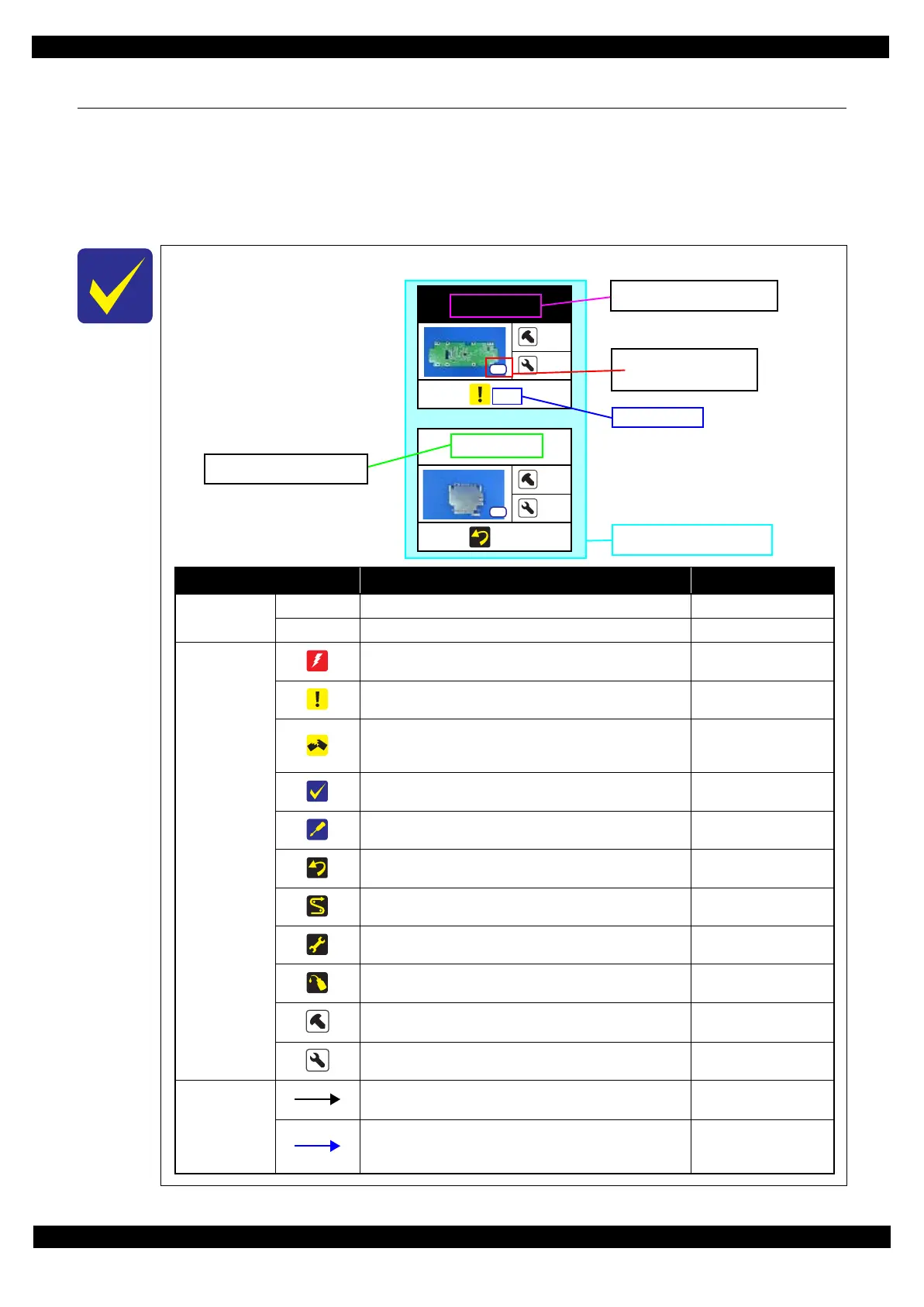
Item Description Reference
Parts/unit name
White-letter
Part/unit supplied as an ASP ---
Black-letter
Part/unit not supplied as an ASP ---
Icon
Indicates a practice or condition that could result in injury or
loss of life if not strictly observed.
Indicates the reference
page in blue-letter
Indicates a practice or condition that could result in damage to,
or destruction of equipment if not strictly observed.
Indicates the reference
page in blue-letter
Indicates the parts that are inevitably broken in the
disassembling procedure, and should be replaced with a new
one for reassembly.
---
Indicates necessary check items in the disassembling/
assembling procedure.
Indicates the reference
page in blue-letter
Indicates supplementary explanation for disassembly is given.
Indicates the reference
page in blue-letter
Indicates particular tasks to keep quality of the units are
required.
Indicates the reference
page in blue-letter
Indicates particular routing of cables is required.
Indicates the reference
page in blue-letter
Indicates particular adjustment(s) is/are required.
Chapter 2 " Adjustment
(p31)"
Indicates lubrication is required.
Chapter 3 " Maintenance
(p71)"
Indicates the number of screws securing the parts/units. ---
Indicates the points secured with other than a screw such as a
hook, rib, dowel or the like
---
Arrowed line
Indicates a disassembling procedure. ---
Indicates a removal procedure for a component of a part or
unit which is necessary to remove when proceeding to the
target part.
---
Shows removal/installation
as a unit/assy. is available.
Reference page
Black letters indicate a part/
unit not supplied as an ASP.
Shows the screw types and
the specified torque in the
“Screw type/torque list”.
White letters indicate a part/
unit supplied as an ASP.
 Loading...