SC-P600 Revision D
Disassembly/Reassembly Routing FFCs/cables 28
SE Group Confidential (Related Staff Only)
1.4 Routing FFCs/cables
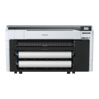
Upper Housing Support Assy
Route the Panel FFCs though the hole of the Upper Housing, and connect it to
the connector on the Panel SUB Board.
Panel SUBBoard
Panel FFCs
Upper Housing
Hole
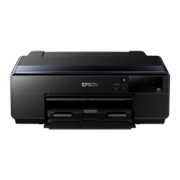
Panel Unit
When routing a cable of the Panel Unit, follow the procedure below.
1. Route the Panel Unit FFC through the hole of the Upper Housing Support
Assy, and through the ferrite core. Fix a fold part of the FFC by the hook.
2. Connect the Panel Unit FFC to the connector on the Panel SUB Board.
3. Fix the grounding wire on the Panel SUB Board with screws, and route
the wire t
hrough the rib and groove
as shown above.
Groove
Rib
Hook
Upper Housing Support Assy
Ferrite Core
Hole
Grounding Wire
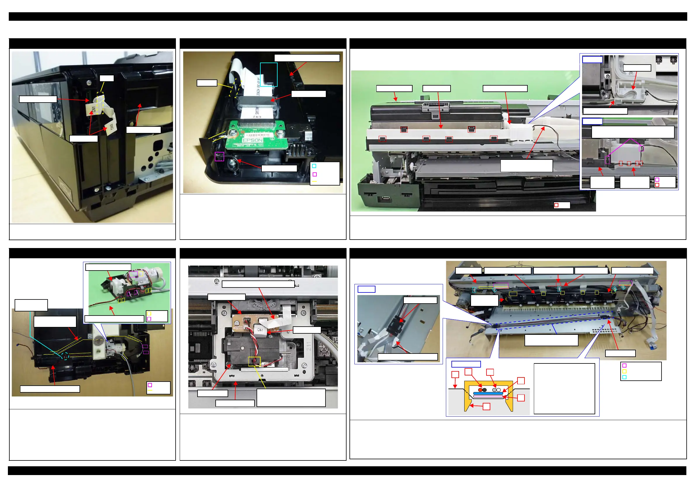
Head FFC
Route the Head FFC through the I/C Holder Unit and Cable Holder Front as shown above.
When routing the I/C Holder Unit Cover Open Sensor Cable, make one turn around the hook of the I/C Holder Unit and route through the ribs (x4) of the
Cable Holder Front, and then make one turn around the hook of the Cable Holder Front.
I/C Holder Unit Cover Open Sensor Cable:
make one turn around hook.
I/C Holder
Unit
Front
Cable Holder
Front
Head FFC
Upper
Cable Holder Front
I/C Holder Unit Head FFC
Rib
Cable Holder Front
I/C Holder Unit Cover
Open Sensor Cable
Decomp Pump Assy
When routing the Decomp Pump Motor Cable through the Decomp Pump
Assy, route the cable through the following ribs and hooks.
• Ribs (x3) and hook on the upper side of the Decomp Pump Assy
• Hooks (x4) and ribs (x2) on the side of the Decomp Pump Assy
Route the following cables through the ribs and grooves of the Lower Housing.
• Decomp Pump Motor Cable
• Stopper Tray Sensor Relay Cable
Decomp Pump Assy
Rib
Hook
Decomp Pump Motor Cable
Stopper Tray
Sensor Relay Cable
Decomp Pump Motor Cable
Make two turns
around hook.
Groove
Rib
CR Support Plate / Ink Selector
Route the following cables/FFCs as shown above and connect them to the
connectors on the CR Relay Board.
Ink Selector Motor Cable (CN2)
Ink Selector Sensor Cable (CN5)
Head FFC (CN1)
CR Encoder / PW Sensor FFC (CN6)
CR Encoder / PW Sensor FFC
Head FFC
Route Ink Selector Motor Cable
and Ink Selector Sensor Cable
through cutout of Ink Selector.
CR Relay Board
Ink Selector
CR Support Plate
Upper side of the Board Assy
Route the Panel FFC through the ribs (x2) along with the reference line as shown above, and secure it with double-sided tape and two pieces of acetate tape A.
Route the PE Sensor Cable through the ribs (x6) of the Release Holder Assy, and secure it with the clamp.
Attach acetate tape B (18 x 30 mm) on the position shown above.
Route the cables through the groove on the Shield Plate Assy Upper Main Board arranging them in the order shown in “cross-section” above, and secure
them with the Cable Holders (x2).
Cable Holder
Acetate Tape B: 18 x 30 mm
Right
Rib
Acetate Tape A
Double-sided tape Reference line
PE Detector
Assy
PE Sensor CableRelease Holder AssyPanel FFC
Cross-section
2
1
3
4
Pump Motor Cable
Roll Paper Guide
Open Sensor Cable
ASF Motor Relay Cable
CR Motor Cable1
2
3
4
5
Cable Holder5
6
6
Shield Plate Assy Upper
Main Board
Cable Holder
Groove of Shield Plate
Assy Upper Main Board
Clamp
 Loading...