SE Group Confidential (Related Staff Only)
Adjustment Details of Adjustments 55
SC-P600 Revision D
2.3.7 Head Angular Adjustment CR/PF
This section describes Head Angular Adjustment CR/PF.
Tools
Adjustment Program
Adjustment procedure
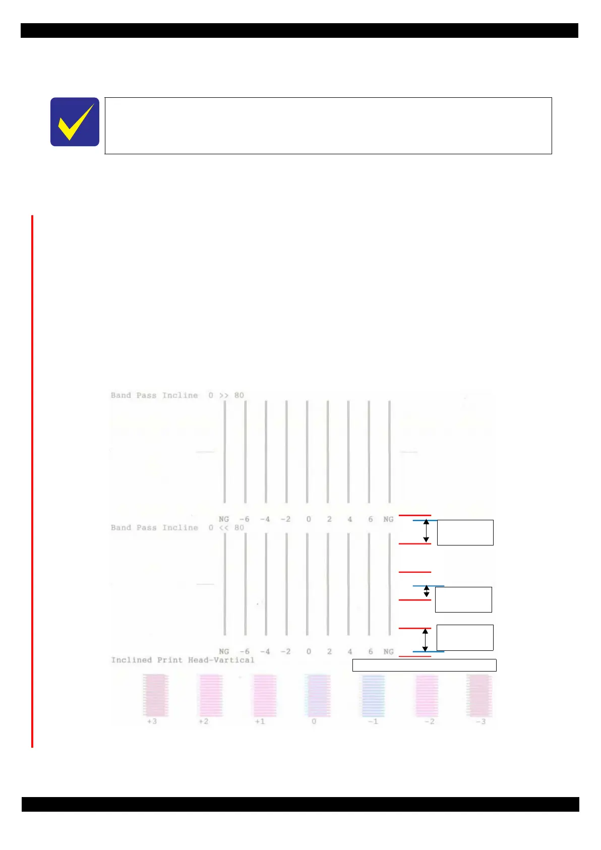
1. Select the Head angular adjustment, and print the adjustment pattern.
2. Examine the printout patterns (
−
6 to
+
6) in the Band pattern, and enter the values of the most straight lines.
Make sure of the each direction. (0 >> 80 and 80 >> 0).
Case 1: the straight line is inside the range from -6 to +6.
Input the values of the most straight line and Press Input button.
Case 2: the straight line is NOT inside the range from -6 to +6.
Refer to Figure 2-25 and Adjust the head angular using Head angular adjustment lever.
Refer to Table 2-4 because the direction of the adjustment is depended on the direction of the printed patter
After adjustment, perform Step 2 again until the straight line is inside the range from -6 to +6.
3. Examine the printout patterns (
+
3 to
−
3) in the Raster Offset pattern, and select the value for the group of
which the gaps between the 2 color bars are the smallest, and then click the Input button.
Figure 2-24. Adjustment Pattern
Basically, set the head angular adjustment lever on the CR Unit on the center position.
bigger gap
-> No good
How to judge Raster Offset pattern
gap
-> good
bigger gap
-> No good
 Loading...