Maintenance 4. Cable
G6 Rev.21 117
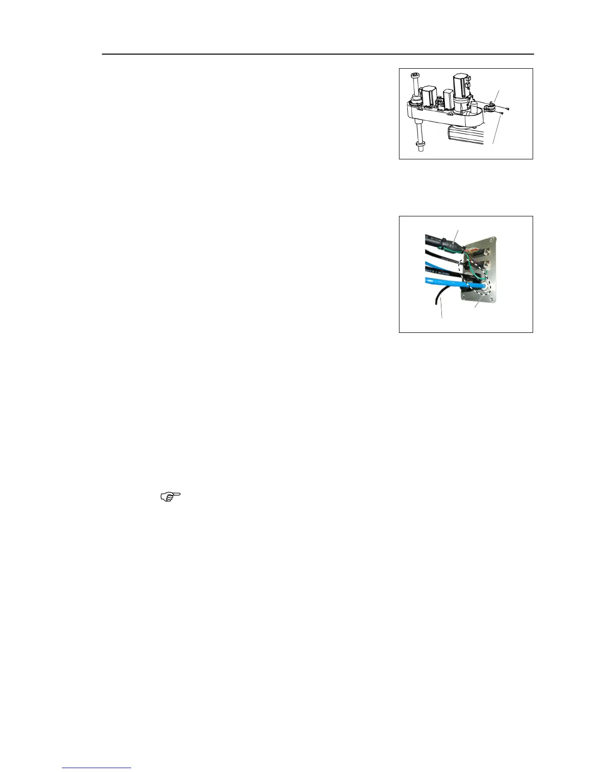
saddle part to the spring plate.
Connect the connectors and the ground wire.
For details, refer to Maintenance: 4.2 Wiring Diagrams.
Bind the excess cables with a wire tie.
the D-sub cable, air tubes, and connector
switch cable to the user plate.
Brake release switch cable
Mount the user plate to the Arm #2 cover.
For details of user plate installation, refer to Maintenance 3.6 User Plate.
Set and secure the Arm #2 cover without the cables being stuck.
For details, refer to Maintenance: 3.1 Arm Top Cover.
Mount the arm caps and side covers for Arm #1.
For details, refer to Maintenance: 3.3 Arm #1 Cover.
Remove the conector plate mounted loosely in the step (8) and remove the spare battery
in theXB11. Then, mount the connector plate.
In this replacement method, calibration is not needed.
However, perform the calibration if it is required.
 Loading...


