T3-B T6-B Maintenance 12. Joint #4
T-B series Maintenance Manual Rev.1 103
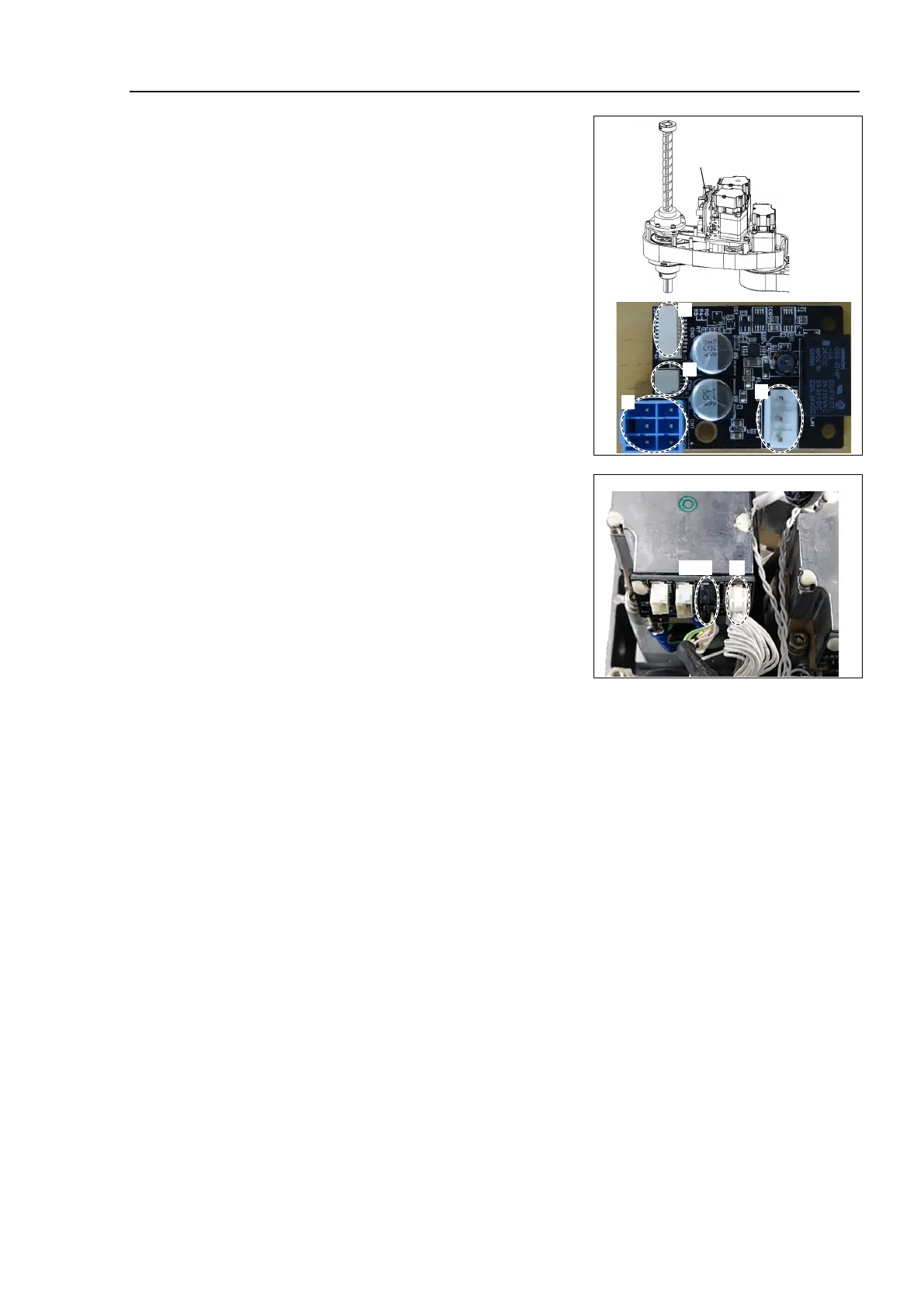
Mount the Joint # 2, 3, 4 AMP board unit.
Sems bolt: 2-M3×10
Connect the following connectors to the
AMP board unit.
A: Power cable connector (×3)
B: AMP cable connector (×3)
C: Motor cable connector (×3)
D: Brake cable connector (×1)
Joint # 2, 3, 4 AMP
board unit
Mount the connector of the Joint #4 motor
unit.
A: AMP cable connector (×1)
B: Signal cable connector
(IN only: ×1)
Reference: 7.7 User Plate
Reference: 7.1 Arm Top Cover
Reference: T-B series Manual T3-B T6-B Manipulator 6.5 LED
When starting the Manipulator for the first time after replacing the motor unit, the motor
unit firmware is automatically updated. DO NOT turn OFF the power until the
Manipulator starts.
When you
connect a motor unit connected to another axis, an error 5009 or 9709 will
occur. To clear the error, enter the following command in [Command Window] and
execute it.
Joint #1: > MUIDReset 1
Joint #2: > MUIDReset 2
Joint #3: > MUIDReset 3
Joint #4: > MUIDReset 4
Reboot the Controller.
Perform the calibration of Joints #3, #4.
Reference: 17. Calibration
 Loading...


