T3-B T6-B Maintenance 12. Joint #4
T-B series Maintenance Manual Rev.1 105
12.2.1 U2 Belt (T6-B)
Press and hold the brake release switch to let the shaft down. Be sure to keep enough
space and prevent the end effector hitting any
peripheral equipment.
The brake release switch affects only Joint #3. When the brake release switch is pressed,
the Joint #3 brake is released.
Be careful of the shaft falling while the brake release switch is being pressed because the
shaft may be lowere
d by the weight of the end effector.
Turn OFF the Manipulator.
Remove the arm top cover.
Reference: 7.1 Arm Top Cover
Reference: 7.7 User Plate
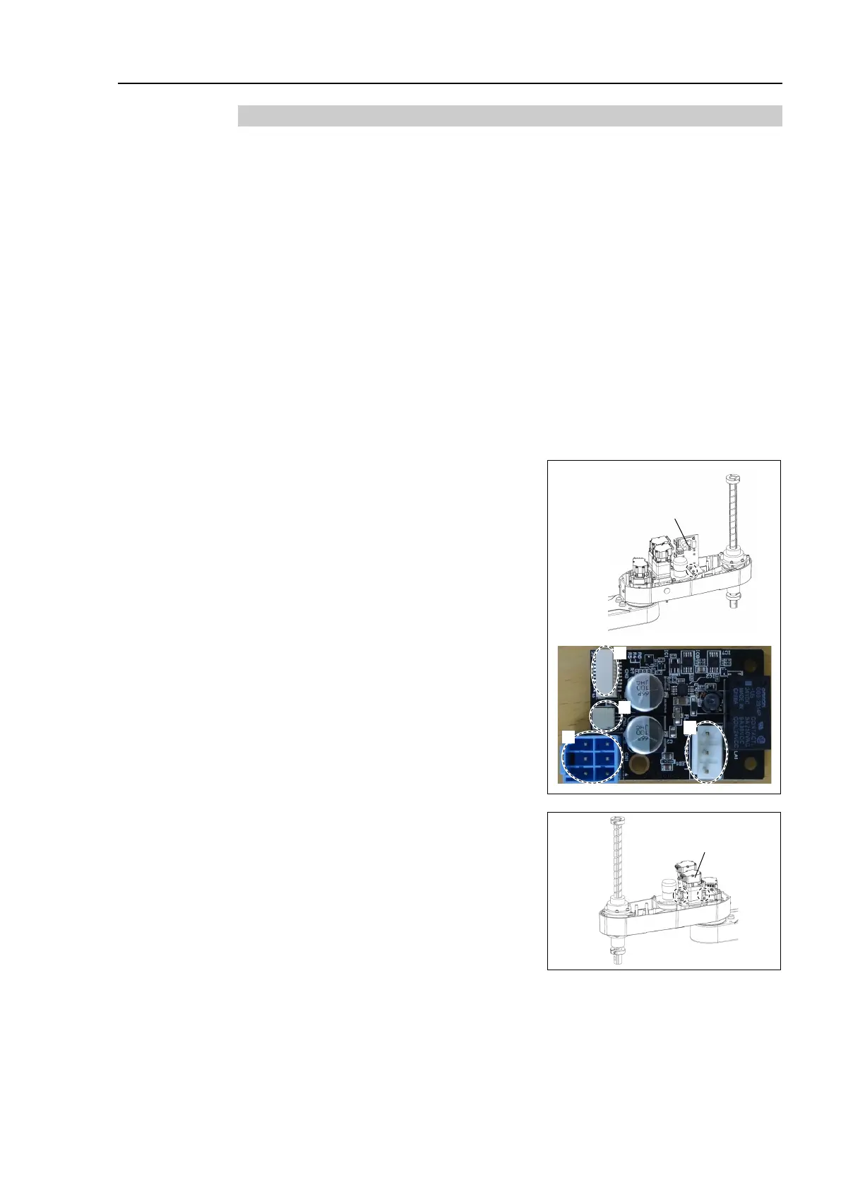
Remove the Joint # 2, 3, 4 AMP board unit.
Sems bolt: 2-M3×10
Remove the following connectors from AMP
board unit.
A: Power cable connector (×3)
B: AMP cable connector (×3)
C: Motor cable connector (×3)
D: Brake cable connector (×1)
Joint # 2, 3, 4 AMP
board unit
Loosen the Joint #3 motor unit mounting bolt.
3-M4×15+M4 washer
 Loading...


