T3-B T6-B Maintenance 17. Calibration
140 T-B series Maintenance Manual Rev.1
17.3 Accurate Calibration of Joint #2
When coordinates for the Manipulator working point require calculation, it is important for
Joint #2 to be calibrated accurately.
If the accuracy of Joint #2 is not obtained through the steps in the section “17.2
Calibration Procedure”, follow the steps below “Calibration Using Right / Left Arm
Orientations” to accurately calibrate Joint #2.
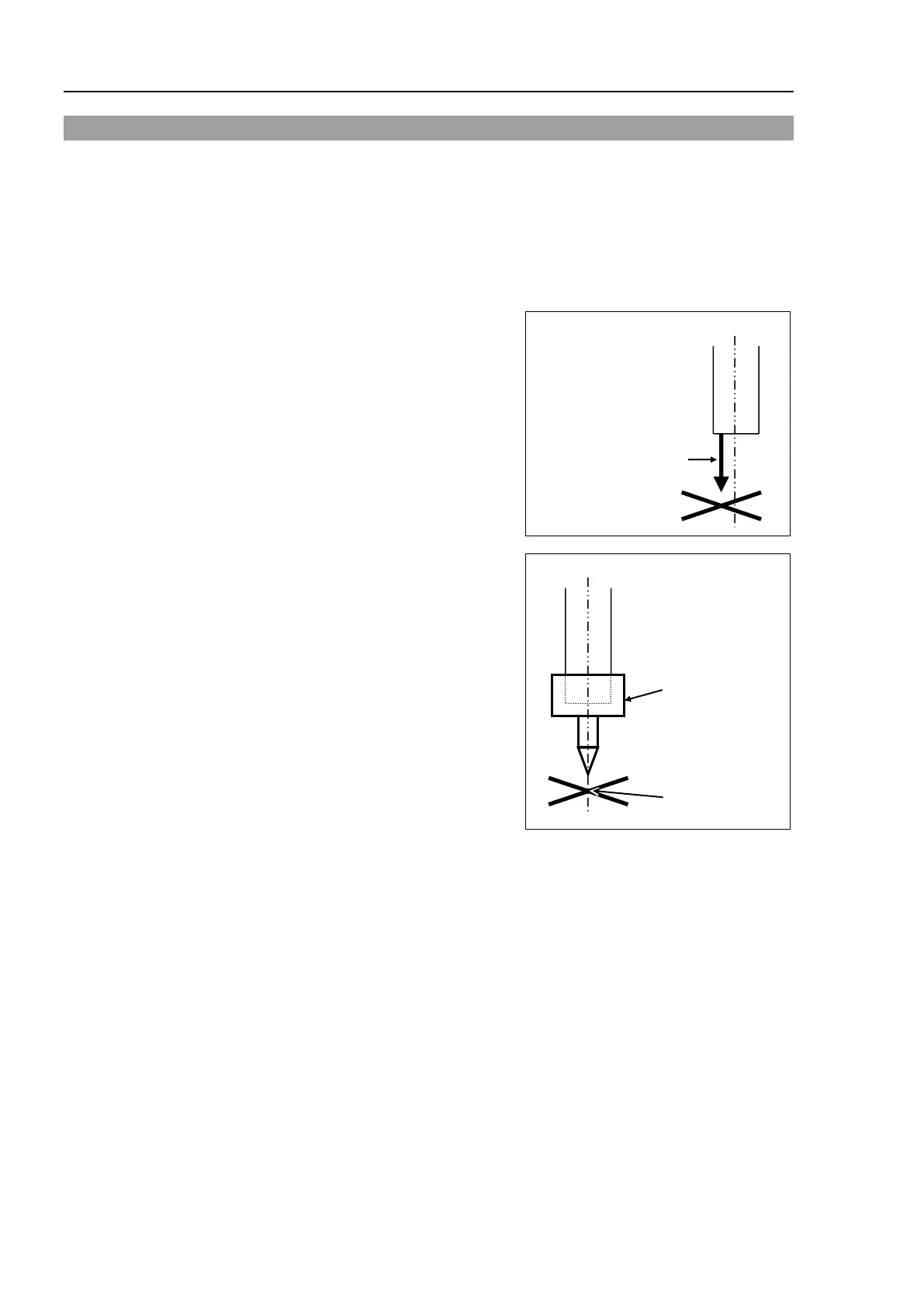
The reference point is the center of th
e ball
screw spline shaft during this calibration.
When there is a misalignment between the
center of the end effector and the center of the
ball screw spline shaft, remove the end effector
and execute the calibration of the shaft.
There is a misalignment
between the center of
the end effector and the
center of the shaft.
Make a calibration jig as shown in the right
figure and attach it on the end of the shaft to
make the center of the shaft clear.
Decide a target point and mark a cross (
×) on it
so that you can easily verify the center of the
shaft after switching the arm pose between right
and left.
Calibration jig at the
end of the shaft
(Example
)
After removing the end effector and executing the calibration, install the end effector and
move the Manipulator to the teaching point to verify whether there is a positional
gap. If
there is a positional gap, fine
-
tune the installation position of the end effector and teach the
point again.
Coordinates for the working point requires calculation in the following cases:
- Teaching the working point by entering the coordinate values (MDI teaching)
- Switching the arm orientation between right and left at a given point
- Using the Pallet command
- Executing CP control (such as liner or circular interpolation)
- Using the Local command
- Pose data specified with relative coordinates <Example: P1+X(100) >
- Vision Guide camera calibrations
 Loading...


