T3-B T6-B Maintenance 12. Joint #4
98 T-B series Maintenance Manual Rev.1
12.1 Replacing Joint #4 Motor
Maintenance
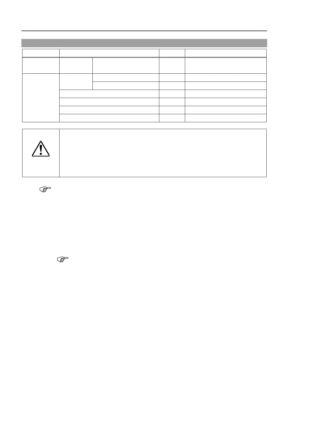
Motor 100W 1 2216545
Tools
Hexagonal
Cross-point screwdriver (No. 2)
U: Belt tension 69 N (7.0 ± 0.5 kgf)
Suitable cord (Length about 800mm)
CAUTION
■
The belt must be installed with proper tension;
otherwise the following problems
If falling below the lower limit : Jumping of the belt gears (position gap)
If exceeding the upper limit : Abnormal noise or vibration (oscillation),
decline in the life of driving parts
A brake is mounted on the Joint #3 motor to prevent the shaft from lowering down due to the
weight of the end effector while the power to the Manipulator is OFF or while the motor is
in OFF status (MOTOR OFF).
Move the shaft down to its lower limit before the replacement procedure following the
removal steps.
4
Press and hold the brake release switch to let the shaft down. Be sure to keep enough
space and prevent the end effector hitting any
peripheral equipment.
The brake release switch affects only Joint #3. When the brake release switch is pressed,
the Joint #3 brake is released.
Be careful of the shaft falling while the brake release switch is being pressed because
the shaft may be lowere
d by the weight of the end effector.
Turn OFF the Manipulator.
Remove the arm top cover.
Reference: 7.1 Arm Top Cover
Reference: 7.7 User Plate
 Loading...


