EPSON
TITLE
SHEET
REVISION
NO.
SHEETNEXT
F
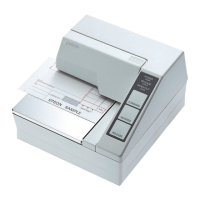
TM-U295/U295P
Specification
(STANDARD)
App.4App.5
APPENDIX C: NOTES ON USING THE DRAWER KICK-OUT CONNECTOR
1) Drawer specifications (see Section 2.2.3,
Drawer kick-out connector
)
Dwawer specifications differ significantly depending on manufacturer and model number. Make
sure that the specifications of the drawer used meet the following conditions when connected to the
drawer kick-out connector. These conditions also apply to any equipment (other than a drawer)
that is connected to the drawer kick-out connector.
Never use a drawer (or other equipment) that does not meet all of the following conditions:
ù
The load, such as a drawer kick-out solenoid, must be connected between pins 4 and 2 or pins 4
and 5 of the drawer kick-out connector. (*1)
ù
When the drawer open/close signal (indicating the state of the drawer) is used, a switch must be
provided between drawer kick-out connector pins 3 and 6. (*2)
ù
The resistance of the load, such as a drawer kick-out solenoid, must be 24
W
or more or the input
current must be 1A or less. (*3)
ù
Make sure to use the 24V power output on drawer kick-out connector pin 4 driving the equipment.
Never connect any other power supply to the drawer kick-out connector. (*4)
The peak current is 1 A. See item 2) below for drive signal duty.
NOTES: (*1): Proper operation is not guaranteed with different connections.
(*2): Proper operation is not guaranteed with different connections or connection to a
component other than a switch.
(*3): Connection to equipment whose resistance is 24
W
or less or whose input current is 1 A
or more may damage the connected equipment as well as the printer.
(*4): Operation is not guaranteed with other power supplies.
 Loading...