EPSON
TITLE
SHEET
REVISION
NO.
SHEETNEXT
F
TM-U295/U295P
Specification
(STANDARD)
19 18
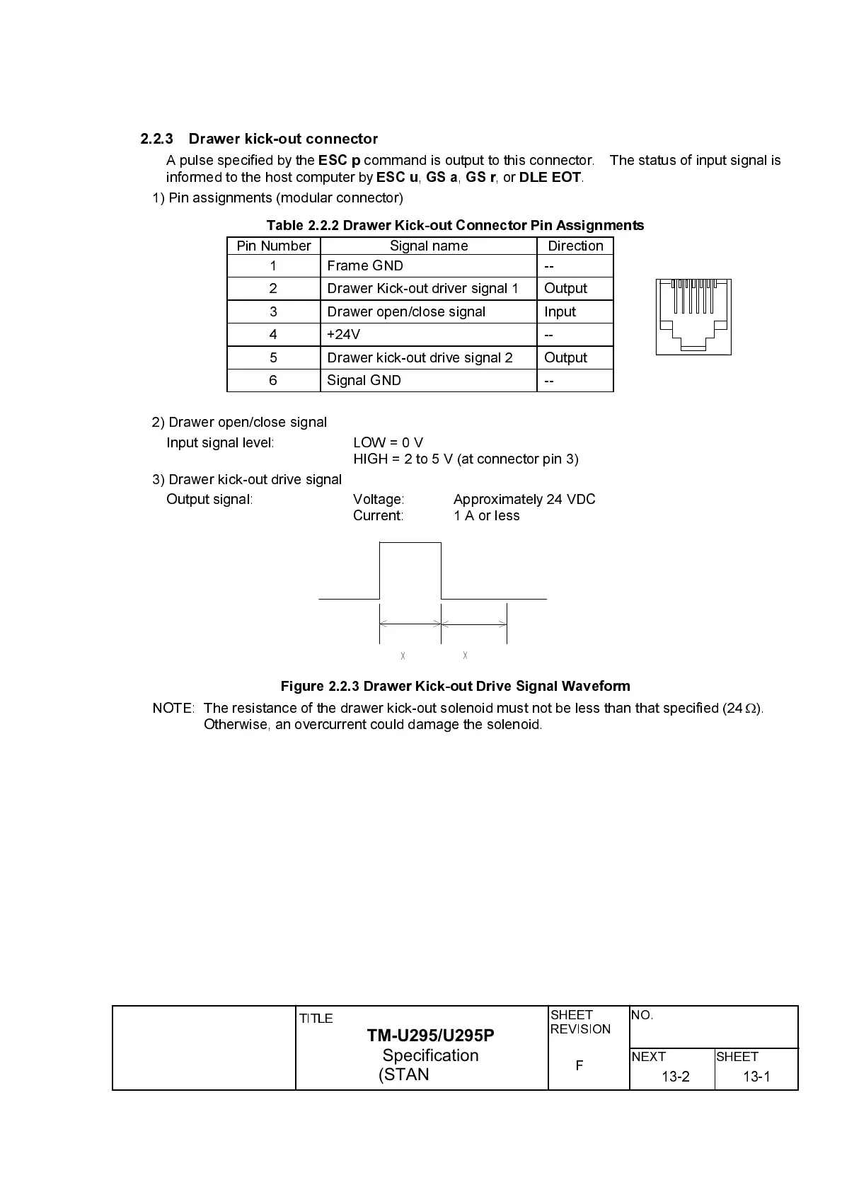
2.2.3 Drawer kick-out connector
A pulse specified by the
ESC p
command is output to this connector. The status of input signal is
informed to the host computer by
ESC u
,
GS a
,
GS r
,or
DLE EOT
.
1) Pin assignments (modular connector)
Table 2.2.2 Drawer Kick-out Connector Pin Assignments
Pin Number Signal name Direction
1 Frame GND --
2 Drawer Kick-out driver signal 1 Output
3 Drawer open/close signal Input
4 +24V --
5 Drawer kick-out drive signal 2 Output
6 Signal GND --
2) Drawer open/close signal
Input signal level: LOW=0V
HIGH=2to5V(atconnector pin 3)
3) Drawer kick-out drive signal
Output signal: Voltage: Approximately 24 VDC
Current: 1 A or less
Figure 2.2.3 Drawer Kick-out Drive Signal Waveform
NOTE: The resistance of the drawer kick-out solenoid must not be less than that specified (24
W
).
Otherwise, an overcurrent could damage the solenoid.
~
~
13-113-2
 Loading...