7
8
E124 10 532365 - Rev.A
1
2
3
4
POWER
C
I
F
Q
120 V
SW1
230 V
PE N L
F1
CON
SW1
CON
F1
115 V ~
120V
230 V ~
230V
Translation of the original instructions
ENGLISH
CON Removable terminal board - Mains power supply
F1
Mains power supply fuse
T 2.5 A 250 V 5x20
SW1 Voltage selector 230 V / 120 V
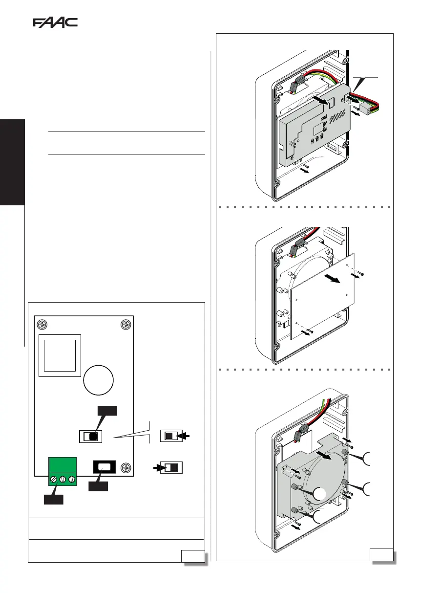
Removing the cover from the board
Remove the E124 board
Remove the cover from the power supply
5.2 COMPONENTS
SWITCHING POWER SUPPLY
The switching power supply is factory set to a nominal
mains voltage of 230 V~.
SETTING THE MAINS VOLTAGE TO 115 V∼
If the mains voltage is 115 V~, the position of the
selector has to be changed.
F
CARRY OUT THE WORK WITH THE POWER SUPPLY DIS-
CONNECTED.
1. (7) Disconnect the POWER connector and remove
the cover of the board.
2. Remove the E124 board.
3. Remove the cover from the power supply.
4. (8) Place the selector switch to 120 V.
5. Put back the parts and insert the POWER connector.
Important
there must be spacers in the posi-
tions marked C, I, Q, F.
Mains voltage selector
Power supply
 Loading...