E124 1 532365 - Rev.A
Translation of the original instructions
ENGLISH
CONTENTS
EU Declaration of conformity ........................... 2
1. INTRODUCTION TO THE INSTRUCTION MANUAL ...... 2
Meaning of the symbols used ........................... 3
2. SAFETY RECOMMENDATIONS ......................... 4
Installer safety ......................................... 4
Transport and storage .................................. 4
Disposal of the product ................................. 4
3. E124 ................................................... 5
3.1 Intended use ......................................... 5
3.2 Limitations of use .................................... 5
3.3 Unauthorised use .................................... 5
3.4 Product identification ................................. 5
3.5 Technical characteristics .............................. 6
4. INSTALLATION REQUIREMENTS ....................... 7
Electrical system ....................................... 7
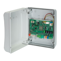
Overall dimensions of the enclosure ..................... 7
5. INSTALLATION ........................................ 8
Tools required ......................................... 8
5.1 Install the enclosure .................................. 8
Remove the cover ...................................... 8
Prepare the cable routing holes ......................... 8
Fasten the enclosure ................................... 9
Install the cover ........................................ 9
5.2 Components ........................................ 10
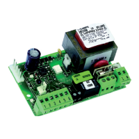
Switching power supply ............................... 10
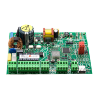
Board E124 ........................................... 11
5.3 Connections ........................................ 12
BUS 2easy (2EASY) devices ............................. 12
Control devices (IN) ................................... 12
Limit switch (FC) ...................................... 12
Gatecoder (ENC)....................................... 13
Configurable outputs (OUT1, OUT2) .................... 13
Flashing light 24 V
"
(LAMP) .......................... 13
Electric lock (LOCK/ OUT1, OUT2) ....................... 13
Motor 1 (MOT1) ....................................... 13
Motor 2 (MOT2) ....................................... 13
XF MODULE ........................................... 14
Radio receiver/decoder board .......................... 14
Emergency batteries (BATTERY) ........................ 14
Mains power supply (CON) ............................. 14
6. START-UP ............................................15
Set-up procedure ..................................... 15
6.1 Turn power on to the board .......................... 15
6.2 Programming the board ............................. 15
6.3 SETUP .............................................. 21
6.4 Configuring movements and timing .................. 22
6.5 Adjusting the anti-crushing system ................... 22
6.6 Final checks ......................................... 23
6.7 Close the enclosure .................................. 23
7. ACCESSORIES .........................................24
7.1 BUS 2easy devices ................................... 24
BUS 2easy control devices ............................. 24
BUS 2easy Photocells, Sensitive edges .................. 25
BUS 2easy encoder .................................... 26
7.2 Registering/Removing BUS 2easy devices ............. 26
7.3 Relay photocells ..................................... 27
Functional test (Fail-Safe) ............................. 27
7.4 Radio controls - SLH/SLHLR .......................... 28
Memorising the master on the board ................... 28
Adding radio controls ................................. 28
7.5 Radio controls - RC/LC ............................... 29
Memorising the radio controls on the board ............ 29
Adding radio controls ................................. 29
7.6 Radio controls - DS .................................. 30
Memorising radio controls on the board ................ 30
7.7 Deleting all radio controls ............................ 30
7.8 Simply Connect ..................................... 31
7.9 Emergency batteries ................................. 32
7.10 External power supply .............................. 32
8. DIAGNOSTICS ........................................33
Signalling LEDS on the board .......................... 33
Firmware version (FW) ................................ 34
Status of the automation .............................. 34
Checking the movement ............................... 34
BUS 2easy status ...................................... 34
Warnings from a programmable output ................ 34
Error codes, Alarms/Info ............................... 35
RESET ................................................ 36
9. MAINTENANCE .......................................37
9.1 Routine maintenance ................................ 37
Cycle counter ......................................... 38
Maintenance requested ............................... 38
9.2 Restoring factory settings ............................ 38
10. OPERATION .........................................39
Commands ........................................... 39
Battery operation (if present) .......................... 39
Detection devices ..................................... 39
Accessories ........................................... 39
Operating logics ...................................... 39
TABLES
1 Technical data ................................................................ 6
2 Basic programming menu .............................................16
3 Advanced programming menu ......................................18
4 SETUP phases ...............................................................21
5 BUS 2easy command DIP switches ................................24
6 BUS 2easy photocells and sensitive edges DIP switches 25
7 Automated system status ..............................................34
8 Errors, Alarms, Info ........................................................35
9 Scheduled maintenance ................................................37
 Loading...