12
13
E124 25 532365 - Rev.A
ON
1 2 3 4
1 0 0 0
CL FSW
1 0 0 1
1 0 1 0
1 0 1 1
1 1 0 0
1 1 1 0
0 0 0 0
OP FSW
0 0 0 1
0 0 1 0
0 0 1 1
0 1 1 1
0 1 0 0
OP/CL FSW
0 1 0 1
1 1 1 1 OPEN
1 1 0 1 CL Edge
0 1 1 0 OP Edge
BUS 2easy BUS 2easy BUS 2easy
2EASY
Translation of the original instructions
ENGLISH
Connecting to the 2EASY terminal board
Do not exceed the maximum load of 500 mA.
The overall length of the BUS 2easy cables must not exceed 100 m.
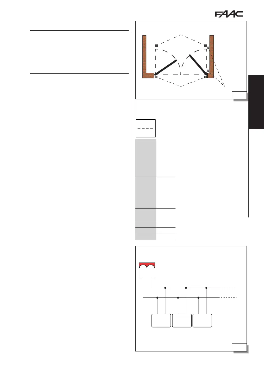
Positioning of photocells
Note: the “Edge” addresses reserved for the
sensitive edges must not be assigned to the
photocells.
BUS 2EASY PHOTOCELLS, SENSITIVE EDGES
!
Photocells are additional type D detection devices
(according to EN 12453) that reduce the likelihood of
contact with the moving leaf. The photocells are not
safety devices according to standard EN 12978. Detec-
tion devices used as safety accessories (e.g. sensitive
edges) to protect against a hazard, must comply with
standard EN 12978.
1. Configure the DIP switches on the transmitter and
receiver to specify the type of operation and assign
an identification code to the pair (ADDRESS).
- DIP switches for BUS 2easy photocells and sensi-
tive edges.
The CLOSING PHOTOCELLS (CL FSW) protect the closing area and
are active during closing.
The OPENING PHOTOCELLS (OP FSW) protect the opening area
and are active during opening.
The OPENING/CLOSING PHOTOCELLS (OP/CL FSW) protect the
entire area of movement and are always active.
The OPEN PHOTOCELLS command OPEN A.
IMPORTANT in a pair of photocells, both the transmitter and the
receiver must have the same DIP switch configuration.
When multiple devices are connected, assigning the same address to
more than one detection device generates an error and prevents the
automation from working (CONFLICT). The addresses of detection
devices do not generate conflicts with control devices and vice versa.
2. Install the devices following the instructions sup-
plied with them.
3. Connect to the 2EASY terminal board using two
cables without polarity.
4. Register the BUS 2easy devices that are connected
(see § specific section).
- note: BUS 2easy registration is also carried out via
the SETUP.
6 BUS 2easy photocells and sensitive edges DIP switches
Key: 0=OFF , 1=ON
 Loading...