16
E124 27 532365 - Rev.A
IN4 o IN5
GND
+24V
+24V
GND
1
2
4
3
2
1
2
5
4
3
2
1
2
4
3
1
2
IN4 o IN5
GND
+24V
+24V
GND
GND
+24V
GND
+24V
IN4 IN5
+24V
GND
1
2
4
3
2
GND
+24V
1
2
5
4
3
2
1
2
4
3
1
2
IN4 IN5
GND
+24V
+24V
GND
GND
+24V
GND
+24V
Translation of the original instructions
ENGLISH
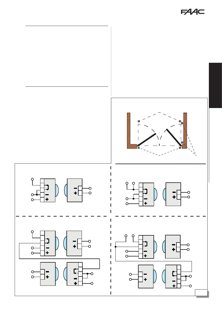
7.3 RELAY PHOTOCELLS
!
Photocells are additional type D detection devices
(according to EN 12453) that reduce the likelihood of
contact with the moving leaf. The photocells are not
safety devices according to standard EN 12978. Detec-
tion devices used as safety accessories (e.g. sensitive
edges) to protect against a hazard, must comply with
standard EN 12978.
Using relay photocells with NC contact. If multiple
photocells are used, the contacts must be connected in
series. If inputs IN4 and IN5 on the board are not used,
they must be bridged to the GND terminal (or to the
output programmed as FAIL-SAFE, if enabled).
Position and connect the photocells according to their
required use:
CL - CLOSING PHOTOCELLS Active during closure in their
detection area.
OP - OPENING PHOTOCELLS Active during opening in
their detection area.
OP/CL - OPENING AND CLOSING PHOTOCELLS Always active
in their detection area.
Connecting 1 pair of closing or opening photocells
Connecting 2 pairs of closing or opening photocells
Connecting 1 pair of opening and closing photocells
Connecting 1 pair of closing photocells and 1 pair of opening and
closing photocells
Positioning the photocells
FUNCTIONAL TEST FAILSAFE
If enabled, the functional test is carried out before
each movement and the board momentarily inter-
rupts the power supply to the transmitters and checks
the change in status of the input. If the test fails, the
board generates an error and prevents the automation
from moving.
1. Connect the negative of the transmitter to the
negative of output OUT1 or OUT2.
2. Enable the FAIL-SAFE test on the output used:
- in Advanced programming,
o1 or o2=01
 Loading...