1. INSTALLATION
1-11
1.6 Display Unit
See the operator's manual for MU-150HD (OMC-44560) and MU-190 (OMC-33670)
for the installation procedure. Keep in mind the following points when selecting a lo-
cation.
• Locate the display unit where no framing is installed immediately forward of the dis-
play unit.
• Locate the display unit where it is easy to view the display in all ambient lighting con-
ditions.
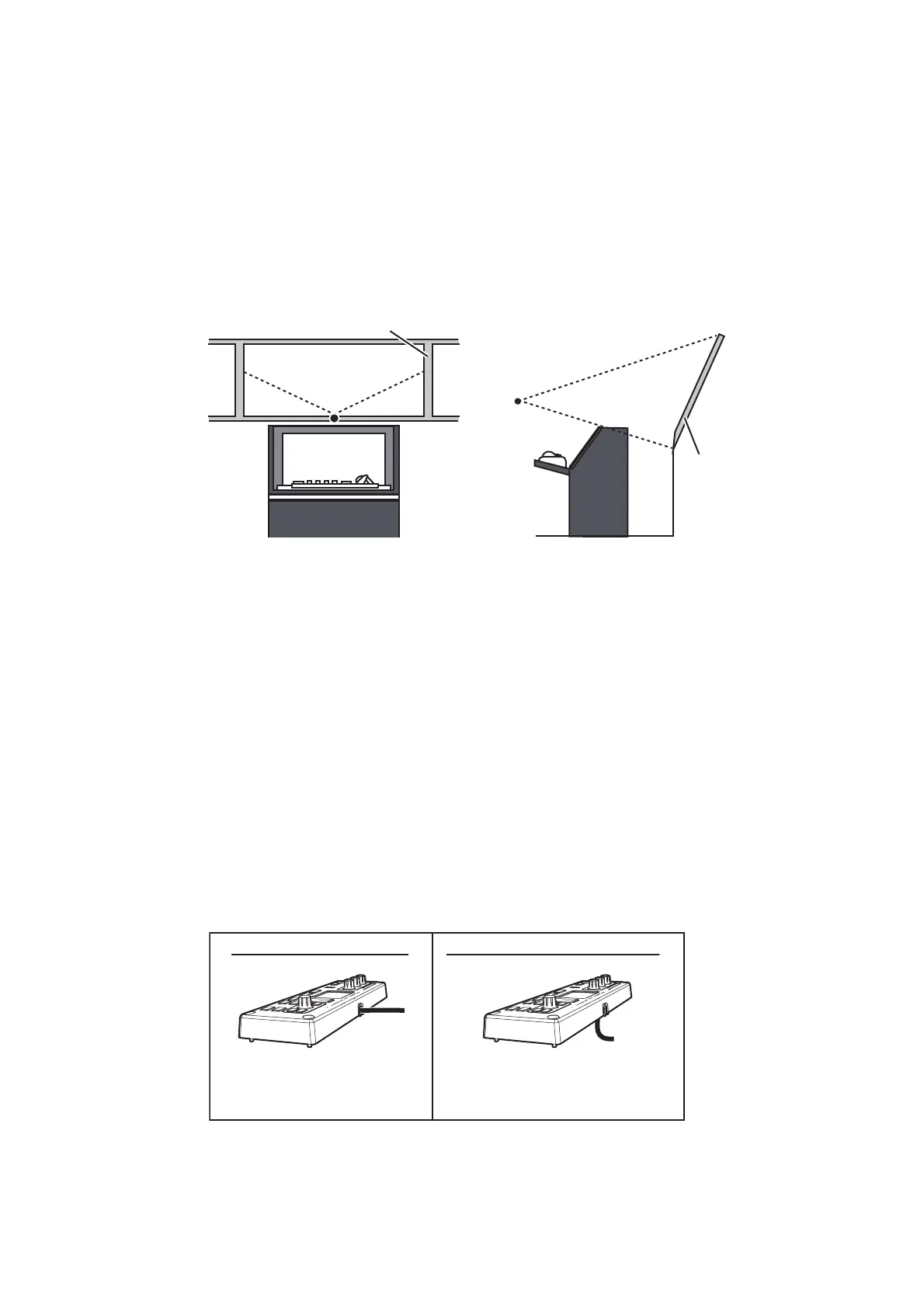
1.7 Control Unit
1.7.1 Mounting considerations
The control unit is designed for desktop/console installations only. Install the control
unit at a distance of 5m or less from the processor unit.
Note: The control unit has a cable for connection to the RCU-030. The cable connec-
tor is supplied with a plastic cover to prevent water intrusion. If this connector is not
used, do not remove the cover. When using this connector, waterproofing the connec-
tion with heat-shrink tubing and vinyl tape.
1.7.2 Mounting
There are two methods you can use to mount the control unit.
Bridge
window
Viewing point
Viewing point
Bridge window
Cable is fed from the
side of the control unit.
Cable is fed from the
rear of the control unit.
Method 1: Factory default Method 2: Modified cable entry
 Loading...