2. WIRING
2-18
2.6 VDR Connection
The processor unit has an RGB port for connection of a VDR. Use the optional RGB
cable (3COX-2P-6C 5m/10m) to connect the VDR.
About the RBG port
• The RGB port and DVI port have their own circuits. This prevents interruption of the
radar picture shown on the main monitor connected to the DVI port, if a fault condi-
tion occurs at the RGB port.
• The processor unit continuously outputs video signals from its DVI and RGB ports.
The operator cannot stop the output.
2.7 Shuttle Ferry Mode
Shuttle ferry mode allows the user to change the screen orientation by 180°. This more
requires an external switch (local supply and install) and the following connection must
be made to the FRP_TB board (03P9601) in the processor unit.
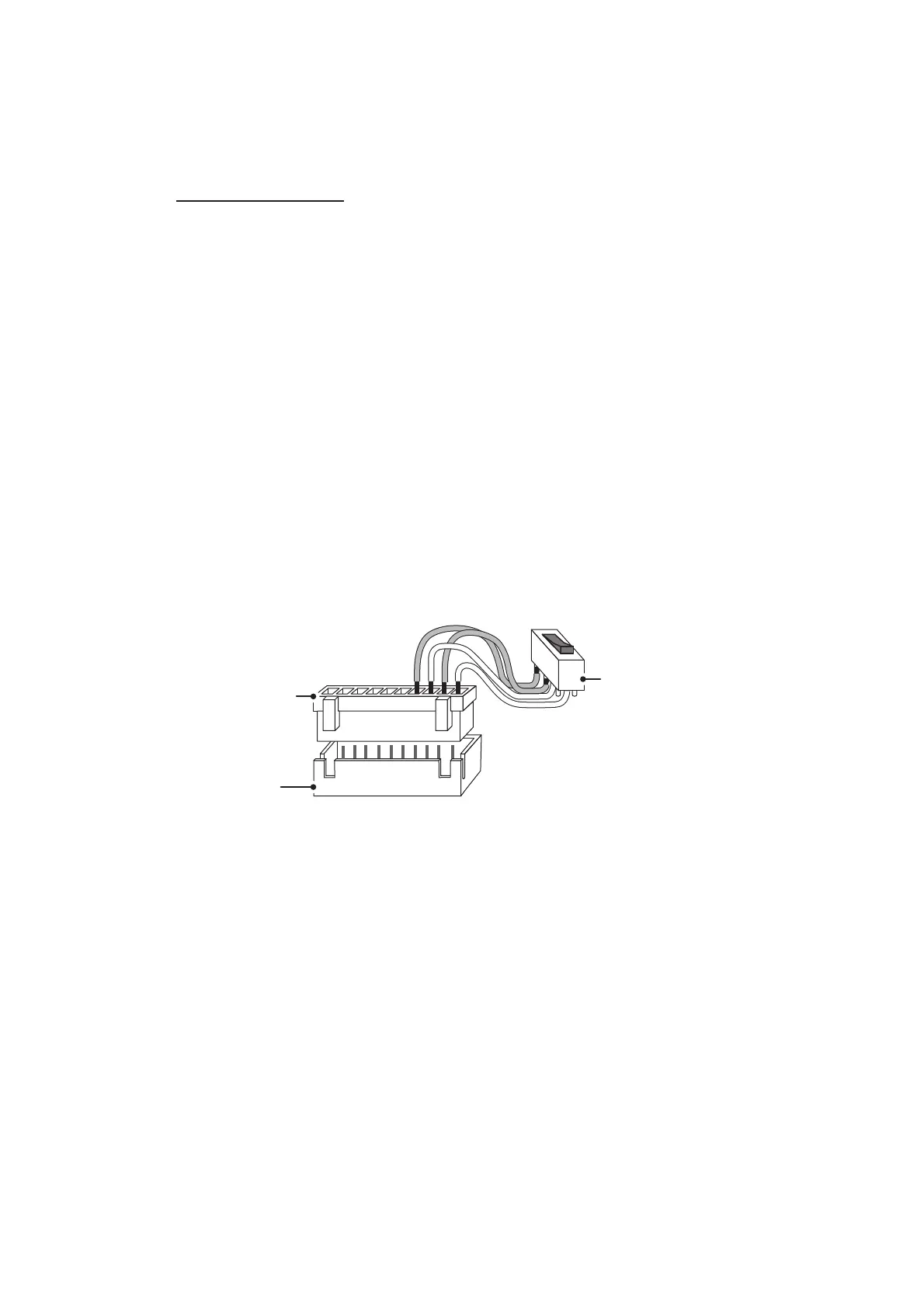
Connect a short-circuit switch to the 1/3 and 2/4 pins on the J609 connector on the
FRP_TB board (XN10P connector required, supplied locally), referring to the figure
below.
ON
OFF
Turns pins 1/3 and 2/4
on or off simultaneously.
XN10P Connector
(Supplied locally)
External switch
(Supplied locally)
Connector J609
(on FRP_TB board)
10 1
 Loading...