2. WIRING
2-10
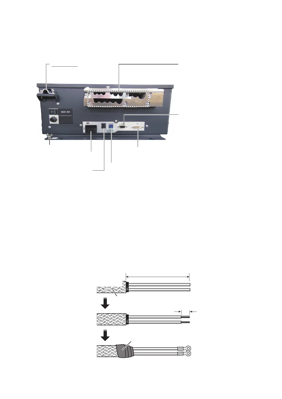
2.4 Processor Unit
The illustration below is the AC specification unit. The DC specification unit does not
have the fuse.
2.4.1 How to fabricate the power cable
1. Remove the armor of the cable by the amount shown in the figure below.
2. Remove the insulation of the cores 10 mm.
3. Fix crimp-on lugs (FV5.5-4, yellow, supplied) to the cores. Cover the end of the
armor with vinyl tape. Lay the cable in the cable clamp on the cable entry side of
the processor unit. Fasten the cable clamp.
4. Fasten the crimp-on lugs to the terminal block inside the unit, referring to the in-
terconnection diagram at the back of this manual.
DVI-D cable
(5 m, to Monitor Unit)
RGB cable (option)
(to external monitor)
TTYCSLA, antenna, control
unit and RW-4864 cables
(For clamping positions,
see the sticker on the
reverse side of the cover.)
* For the antenna cable of
the FAR-15x8, remove the
spacer to insert the cable.
LAN cable (UTP, CAT5e, local supply)
(to other radar or HUB switch)
(Fasten the cable to the post below
the connector with a cable tie.)
Power cable
DC power: DPYC-6
AC power: DPYC-2.5
Ground terminal
(Use IV-8sq.,
local supply)
USB connector
( No use.)
SD card
slot
*
FUSE
8A
Armor
DC power: DPYC-6
AC power: DPYC-2.5
AC: 50 mm
DC: 60 mm
Taping
10
 Loading...