3. ADJUSTMENTS
3-5
3.7 RADAR INSTALLATION Menu
This section provides descriptions of the [RADAR INSTALLATION] menu items not
previously mentioned.
3.7.1 OWN SHIP INFO menu
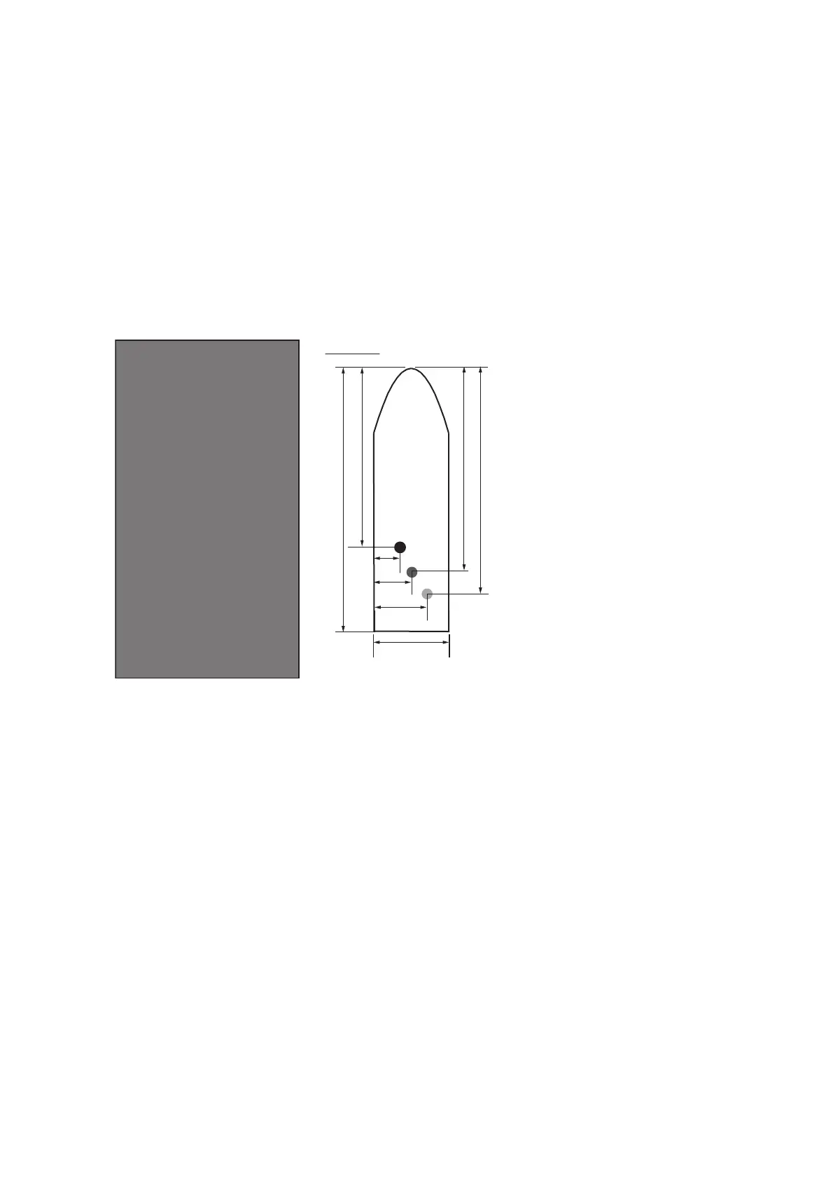
Enter the length and width of the ship, and scanner, GPS antenna and conning posi-
tions, referring to the description and figure below.
Note: This radar uses the CCRP=CONNING POSITION and ANT=SCANNER POSI-
TION as the reference points for measurements and calculations. The commissioning
engineer should understand this point, and enter own ship information accordingly.
[LENGTH/WIDTH]: Enter the ship’s length and width.
[SCANNER POSITION]: Enter the distance from the scanner to both bow and port.
[GPS 1 ANT POSITION]: Enter the distance from the GPS antenna to both bow and
port. If a 2nd GPS antenna is installed, enter its position in [GPS 2 ANT POSITION].
[CONNING POSITION]: Enter the distance from the conning position to both bow and
port.
L1
L1: Ship length
W1: Ship width
L2: Conning position (from bow)
W2: Conning position (from port)
L3: Scanner position (from bow)
W3: Scanner position (from port)
L4: GPS antenna position (from bow)
W4: GPS antenna position (from port)
W1
L2
W2
W3
W4
L3
L4
Example
[OWN SHIP INFO]
1 BACK
2 LENGTH/WIDTH
LENGTH 0m
WIDTH 0m
3 SCANNER POSITION
BOW 0m
PORT 0m
4 GPS1 ANT POSITION
BOW 0m
PORT 0m
5 GPS2 ANT POSITION
BOW 0m
PORT 0m
6 CONNING POSITION
BOW 0m
PORT 0m
 Loading...