1. MOUNTING, WIRING
11
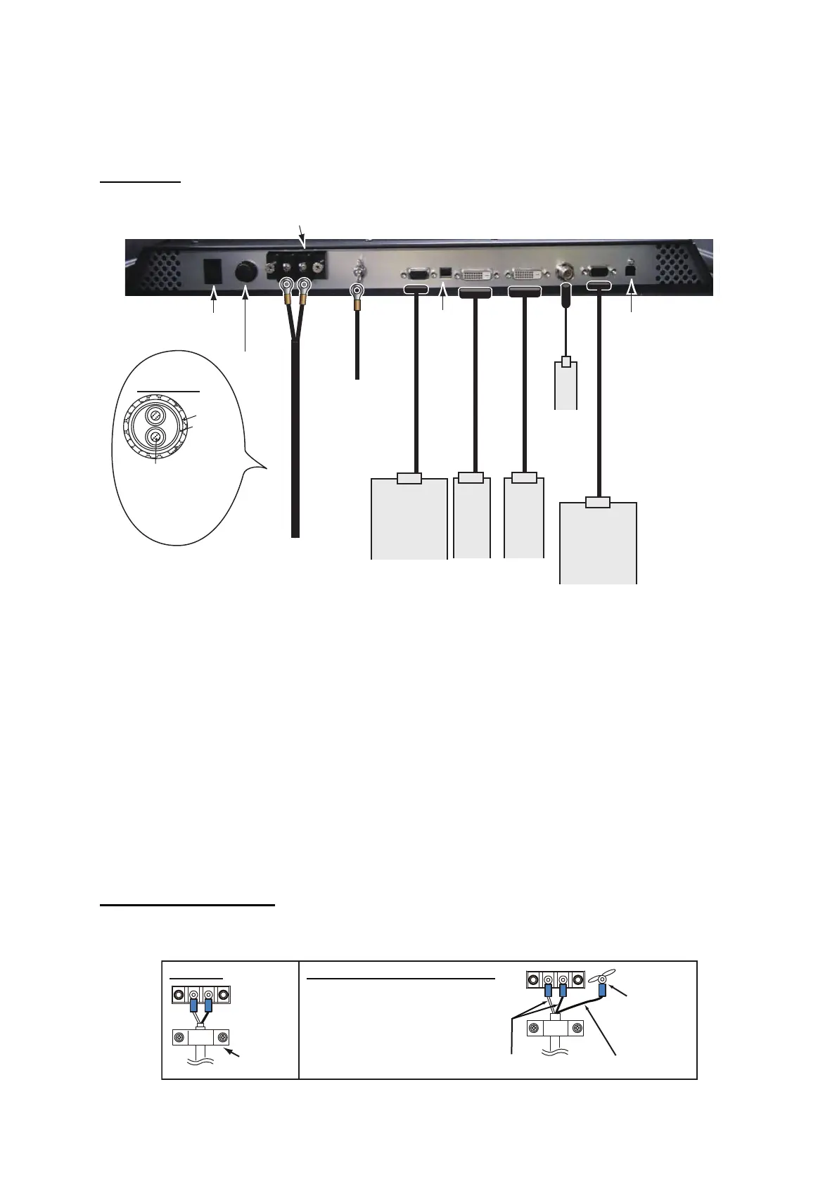
1.8 Wiring
Refer to the figure below and the interconnection diagram at the back of this manual to connect
cables.
Connector
*1: Attach a crimp-on lug (inner dia. 4) for monitor unit side. Make the length of the ground wire
as short as possible.
*2: Slide switch
Note: Turn the slide switch off when you connect equipment to both the DVI and RGB ports.
*3: BRILL CTRL port
No use. Do not remove the sticker from the connector.
*4: DVI-D/D S-LINK 10M
This is not available for UXGA signal.
How to fix power cable
Fix the power cable with the cable clamp to prevent it from loosening.
• ON (upward): Allow digital signal from external equipment to control on/off of the monitor unit.
• OFF (downward): Set to OFF for analog RGB signal.
FSV-84/84L
FSV-30/S-BB
FSV-24/S-BB
FCV-30
FCV-1200L/M
FSV-84/84L
FSV-30/S-BB
FSV-24/S-BB
FCV-30
FCV-1200L/M
FAR-28x7
FEA-2807
FCR-28x7
MFDBB
FMD-3300
FCR-28x9
FAR-33x0
FAR-28x7
FEA-2807
FCR-28x7
MFDBB
FMD-3300
FCR-28x9
FAR-33x0
FEA-2807, FCR-28x7
(with RS-232C)
or
FMD-3300, FCR-28x9
FAR-33x0
(with RS-485)
FEA-2807, FCR-28x7
(with RS-232C)
or
FMD-3300, FCR-28x9
FAR-33x0
(with RS-485)
The bottom of the rear of the monitor unit
RGB signal
3COX-2P-6C
5 m/10 m (option)
RGB signal
3COX-2P-6C
5 m/10 m (option)
RGB signal
3COX-2P-6C
5 m/10 m (option)
Digital signal
DVI-D/D S-LINK
5 m (standard)/
10 m *
4
(option)
Digital signal
DVI-D/D S-LINK
5 m (standard)/
10 m *
4
(option)
Digital signal
DVI-D/D S-LINK
5 m (standard)/
10 m *
4
(option)
Composite
signal cable
Composite
signal cable
Composite
signal cable
CCD camera
DVD recorder
CCD camera
DVD recorder
CCD camera
DVD recorder
BRILL CTRL port *
3
BRILL CTRL port *
3
BRILL CTRL port *
3
IV-8 sq
(local supply) *
1
IV-8 sq
(local supply) *
1
IV-8 sq
(local supply) *
1
To ground
terminal on hull
DPYC-1.5
(or equivalent)
DPYC-1.5
(or equivalent)
DPYC-1.5
(or equivalent)
100-230 VAC
Slide
switch *
2
Slide
switch *
2
Slide
switch *
2
Power
switch
Fuse
RS-232C cable
(Max. 10 m)
or
RS-485 cable
(Max. 10 m)
RS-232C cable
(Max. 10 m)
or
RS-485 cable
(Max. 10 m)
RS-232C cable
(Max. 10 m)
or
RS-485 cable
(Max. 10 m)
DPYC-1.5
φ = 11.7 mm
Armor
Sheath
Conductor
S = 1.5 mm
2
φ = 1.56 mm
Attach the Terminal Board Gear Cover
again after connecting cables.
MU-231
Cable
clamp
Length: 50 mm
Length: 70 mm
Local supply
Replace MU-231CE with MU-231
Cut the connector of the power
cable (15-565, supplied on the
MU-231CE). Attach a crimp-on
lug (supplied on the MU-231)
to each cable core then
connect the cables as in the
figure at right.
 Loading...