Figure 4: AND logic equation
AND Logic application example
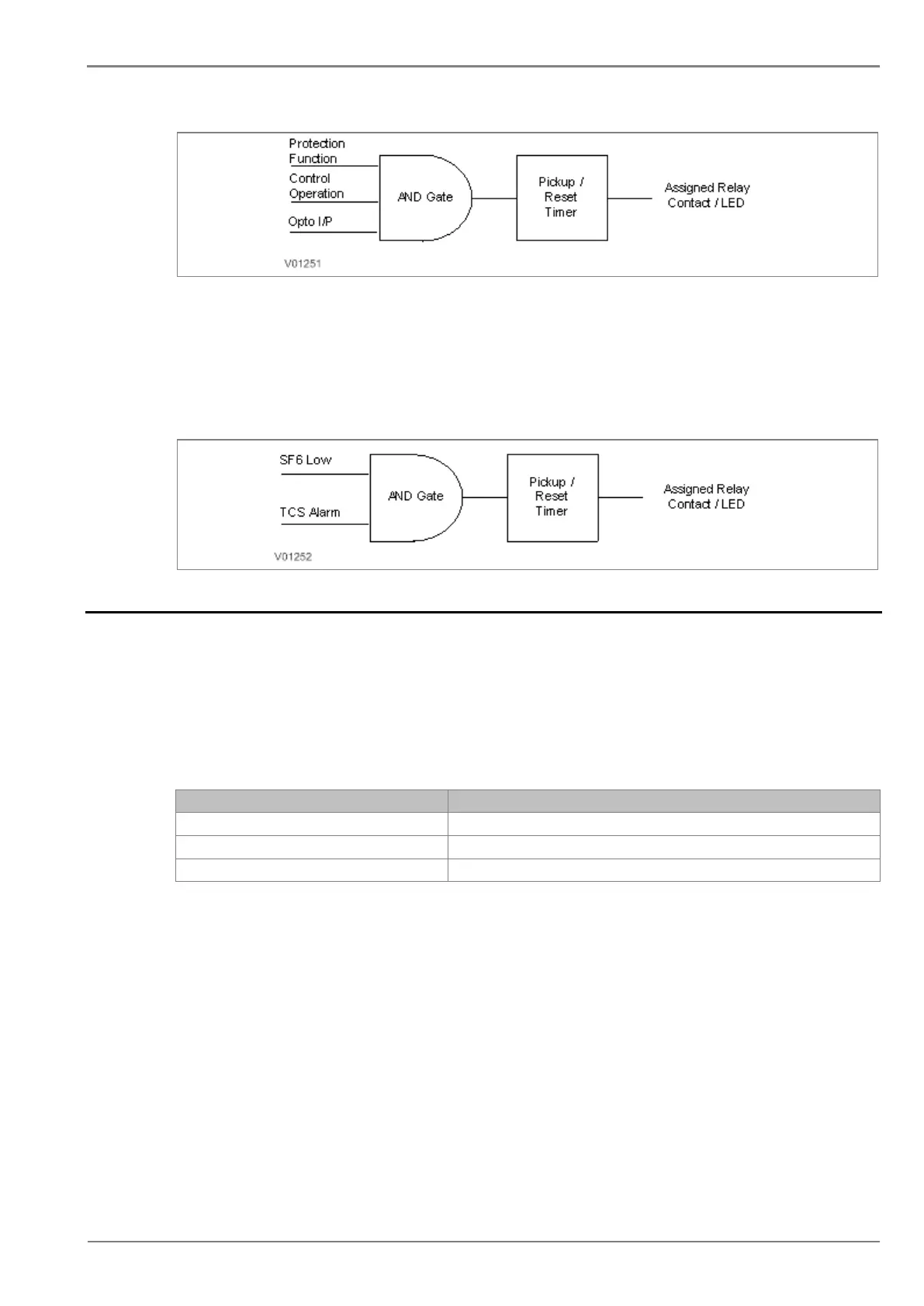
The figure below is an example for AND logic implementation in the relay. There are two inputs to the
AND equations, one is SF6 Gas low signal which is externally wired to Opto I/P 1 of relay and other
input is TCS Alarm which is internally generated signal. Both signals are assigned to AND logic
equation and when both the input signals are high, then the output of AND logic equation will be high.
This output can be used to block all protection functions through external wiring.
Figure 5: AND logic equation application example
2.8 CB Monitoring
Periodic maintenance of circuit breakers is necessary to ensure that the trip circuit and mechanism
operate correctly and also that the breaking capability has not been compromised due to previous fault
interruptions. Generally, such maintenance is based on a fixed time interval. These methods of
monitoring circuit breaker condition give a rough guide only and can provide early indications of
maintenance required. The relays record various statistics related to each circuit breaker trip
operation, allowing a more accurate assessment of the circuit breaker condition.
Relay records following circuit breaker operation statistics:-
“Breaker Opening Time”- This is a circuit breaker opening time in ms.
“Breaker Operation Counter”- This counter indicates numbers of CB operations.
TC “Trip Counter” -This counter indicates number of protection trips.
The above counters can be reset to zero, after maintenance inspection and overhaul.
2.8.1 CB Open Supervision
Slow CB operation indicates the need for mechanism maintenance. Alarm threshold (CB Open Time)
is provided to enforce this and can be set in the range of 50msec to 1 sec. This time relates to the
interrupting time of the circuit breaker and includes relay trip contact operating time, CB main contact
operation time and CB auxiliary contact operating time.
The relay starts internal timer as soon as any protection function is operated. Relay monitors the CB
open contact status and stops the timer as soon as the CB open feedback is received by the relay. If
this measured time is more than setting “CB Open Time”, then relay generates CB Open
Supervision alarm. An alarm message is displayed on LCD display and the START LED starts
blinking. The associated event is stored in Event Record. In the event the measured Breaker opening
time is less than the setting “CB Open Time”, the timer is reset and no alarm is generated.
 Loading...


