2.3.12 I/O Configuration Menu
2.3.12.1 View/Edit Settings
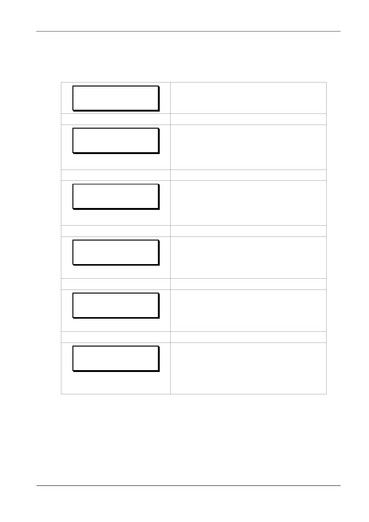
IO CONFIGURATION
Password protected window for “OP CONTACT CONFIGURATION’’
settings: Relay, LED Green, LED Red, AND Logic and Opto I/P.
Relay : 4321
Gen Strt 0000
Editable setting
By using the (5) or (6) key, the output relay RL1 – RL4 can be set for
desired function.
‘1’ corresponds to RL1, ‘2’ corresponds to RL2,…’4’ corresponds to RL4
Set the value ‘1’ for assigned / ‘0’ for not assigned under the numbers
representing output relay.
LED G : 65
Gen Strt 00
Editable setting
By using the (5) or (6) key, LED GREEN can be set for desired
function.
‘5’ corresponds to LED L5, ‘6’ corresponds to LED L6
Set the value ‘1’ for assigned / ‘0’ for not assigned under the numbers
representing LED GREEN.
LED R : 65
Gen Strt 00
Editable setting
By using the (5) or (6) key, LED RED can be set for desired function.
‘5’ corresponds to LED L5, ‘6’ corresponds to LED L6
Set the value ‘1’ for assigned / ‘0’ for not assigned under the numbers
representing LED RED.
AND Logic : DCBA
Gen Strt 0000
Editable setting
By using the (5) or (6) key, the AND Logic function (A,B,C,D) can
be set for desired function.
Set the value ‘1’ for assigned / ‘0’ for not assigned under the letters
representing AND Logic function.
Opto I/P : 4321
Rem. Rst. 0000
Editable setting
By using the (5) or (6) key, Opto inputs can be set for desired
function.
‘1’ corresponds to Opto I/P S1, ‘2’ corresponds to Opto I/P S2,…’4’
corresponds to Opto I/P S4
Set the value ‘1’ for assigned / ‘0’ for not assigned under the numbers
representing Opto I/Ps.
2.3.12.2 List of the submenus for Relay Output, LEDs and AND Logic configuration
2.3.12.2.1 Relay Output Configuration
Relay outputs can be assigned by selecting any function available in the submenus. There are in
all 4 numbers of output Relays identified as RL1 to RL4.
 Loading...


