5-72 C60 Breaker Protection System GE Multilin
5.2 PRODUCT SETUP 5 SETTINGS
5
disconnected. The method is accurate only if this setting matches perfectly the actual system impedance during the fault. If
the system exhibits too much variability, this approach is questionable and the fault location results for single-line-to-ground
faults shall be trusted with accordingly. It should be kept in mind that grounding points in vicinity of the installation impact
the system zero-sequence impedance (grounded loads, reactors, zig-zag transformers, shunt capacitor banks, etc.).
5.2.8 OSCILLOGRAPHY
a) MAIN MENU
PATH: SETTINGS PRODUCT SETUP OSCILLOGRAPHY
Oscillography records contain waveforms captured at the sampling rate as well as other relay data at the point of trigger.
Oscillography records are triggered by a programmable FlexLogic operand. Multiple oscillography records can be captured
simultaneously.
The NUMBER OF RECORDS is selectable, but the number of cycles captured in a single record varies considerably based on
other factors, such as sample rate and the number of operational modules. There is a fixed amount of data storage for
oscillography; the more data captured, the less the number of cycles captured per record. See the
ACTUAL VALUES
RECORDS OSCILLOGRAPHY menu to view the number of cycles captured per record. The following table provides sam-
ple configurations with corresponding cycles/record. The minimum number of oscillographic records is three.
A new record can automatically overwrite an older record when
TRIGGER MODE is set to “Automatic Overwrite.”
Set the
TRIGGER POSITION to a percentage of the total buffer size (for example, 10%, 50%, 75%, and so on). A trigger posi-
tion of 25% consists of 25% pre- and 75% post-trigger data. The
TRIGGER SOURCE is always captured in oscillography and
can be any FlexLogic parameter (element state, contact input, virtual output, and so on). The relay sampling rate is 64 sam-
ples per cycle.
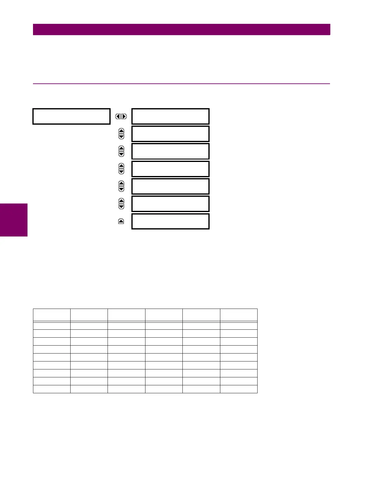
OSCILLOGRAPHY
NUMBER OF RECORDS:
5
Range: 1 to 64 in steps of 1
MESSAGE
TRIGGER MODE:
Automatic Overwrite
Range: Automatic Overwrite, Protected
MESSAGE
TRIGGER POSITION:
50%
Range: 0 to 100% in steps of 1
MESSAGE
TRIGGER SOURCE:
Off
Range: FlexLogic operand
MESSAGE
AC INPUT WAVEFORMS:
16 samples/cycle
Range: Off; 8, 16, 32, 64 samples/cycle
MESSAGE
DIGITAL CHANNELS
MESSAGE
ANALOG CHANNELS
Table 5–9: OSCILLOGRAPHY CYCLES/RECORD EXAMPLE
RECORDS CT/VTS SAMPLE
RATE
DIGITAL
CHANNELS
ANALOG
CHANNELS
CYCLES PER
RECORD
3 1 32 32 16 2399
3 1 64 32 16 1450
161 323216666
161 643216402
321 323216352
321 643216213
3 2 32 32 16 1516
3 2 64 32 16 851
162 323216421
 Loading...


