GE Multilin C60 Breaker Protection System 6-21
6 ACTUAL VALUES 6.3 METERING
6
The metered frequency values are displayed in this menu. The "SRC 1" text will be replaced by whatever name was pro-
grammed by the user for the associated source (see SETTINGS SYSTEM SETUP SIGNAL SOURCES).
SOURCE FREQUENCY is measured via software-implemented zero-crossing detection of an AC signal. The signal is either a
Clarke transformation of three-phase voltages or currents, auxiliary voltage, or ground current as per source configuration
(see the SYSTEM SETUP POWER SYSTEM settings). The signal used for frequency estimation is low-pass filtered. The
final frequency measurement is passed through a validation filter that eliminates false readings due to signal distortions and
transients.
6.3.3 SYNCHROCHECK
PATH: ACTUAL VALUES METERING SYNCHROCHECK SYNCHROCHECK 1(4)
If a synchrocheck function setting is "Disabled", the corresponding actual values menu item is not displayed.
6.3.4 TRACKING FREQUENCY
PATH: ACTUAL VALUES METERING TRACKING FREQUENCY
The tracking frequency is displayed here. The frequency is tracked based on the selection of the reference source with the
FREQUENCY AND PHASE REFERENCE setting in the SETTINGS SYSTEM SETUP POWER SYSTEM menu. See the Power
System section of chapter 5 for details.
6.3.5 FLEXELEMENTS
PATH: ACTUAL VALUES METERING FLEXELEMENTS FLEXELEMENT 1(8)
The operating signals for the FlexElements are displayed in pu values using the following definitions of the base units.
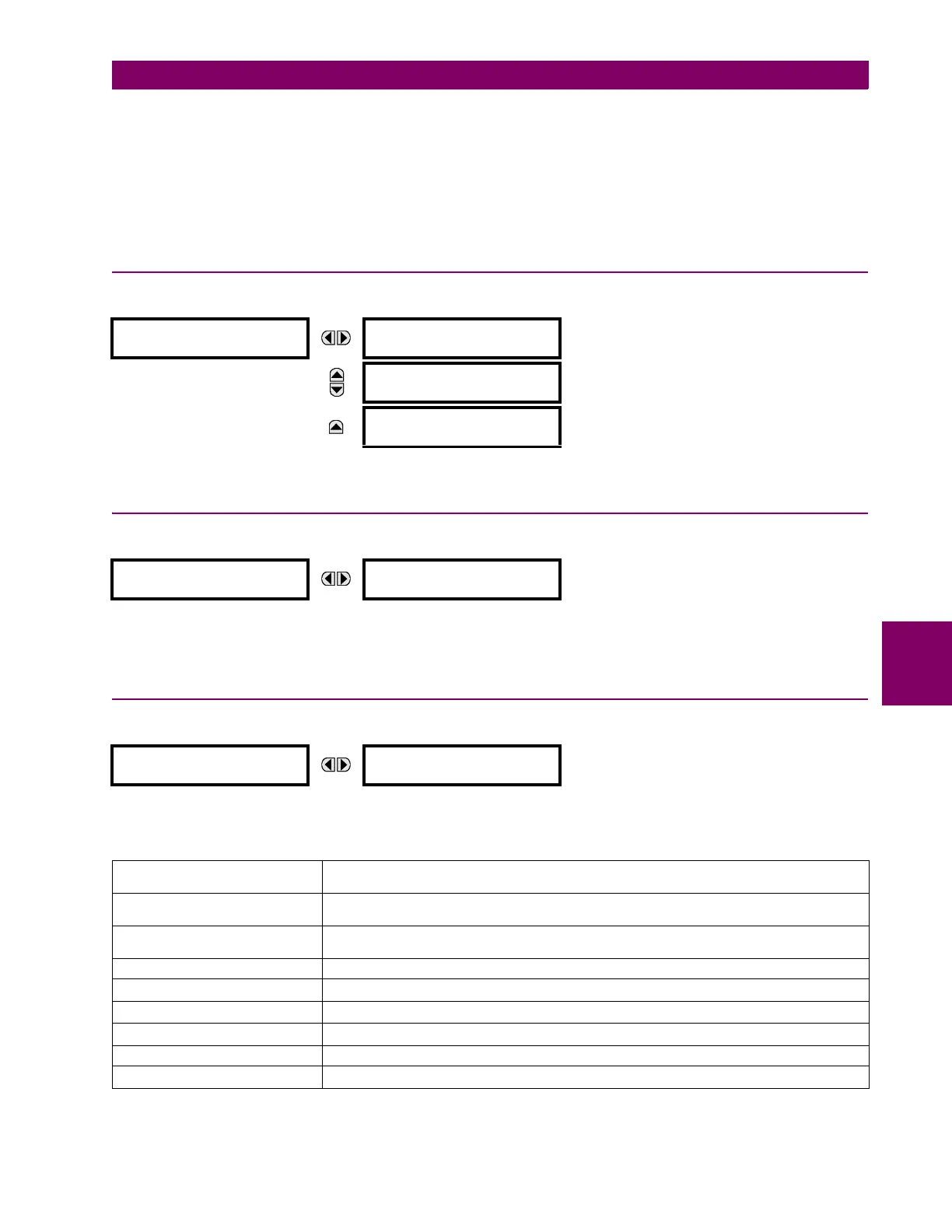
SYNCHROCHECK 1
SYNCHROCHECK 1 DELTA
VOLT: 0.000 V
MESSAGE
SYNCHROCHECK 1 DELTA
PHASE: 0.0°
MESSAGE
SYNCHROCHECK 1 DELTA
FREQ: 0.00 Hz
TRACKING FREQUENCY
TRACKING FREQUENCY:
60.00 Hz
FLEXELEMENT 1
FLEXELEMENT 1
OpSig: 0.000 pu
Table 6–2: FLEXELEMENT BASE UNITS (Sheet 1 of 2)
BREAKER ACC ARCING AMPS
(Brk X Acc Arc Amp A, B, and C)
BASE = 2000 kA
2
× cycle
BREAKER ARCING AMPS
(Brk X Arc Amp A, B, and C)
BASE = 1 kA
2
× cycle
DCmA BASE = maximum value of the
DCMA INPUT MAX setting for the two transducers configured
under the +IN and –IN inputs.
FAULT LOCATION BASE = Line Length as specified in Fault Report
FREQUENCY f
BASE
= 1 Hz
PHASE ANGLE ϕ
BASE
= 360 degrees (see the UR angle referencing convention)
POWER FACTOR PF
BASE
= 1.00
RTDs BASE = 100°C
SOURCE CURRENT I
BASE
= maximum nominal primary RMS value of the +IN and –IN inputs
 Loading...


