Components and Functions (Theory)
5-10 Invenia ABUS 2.0 – System Setup and Basic Service Manual
4700-0043-00 Rev. 4
Ultrasound Box
Major components and their functions and operation
The main items in the Ultrasound Box are:
Ultrasound Box thermal and cooling
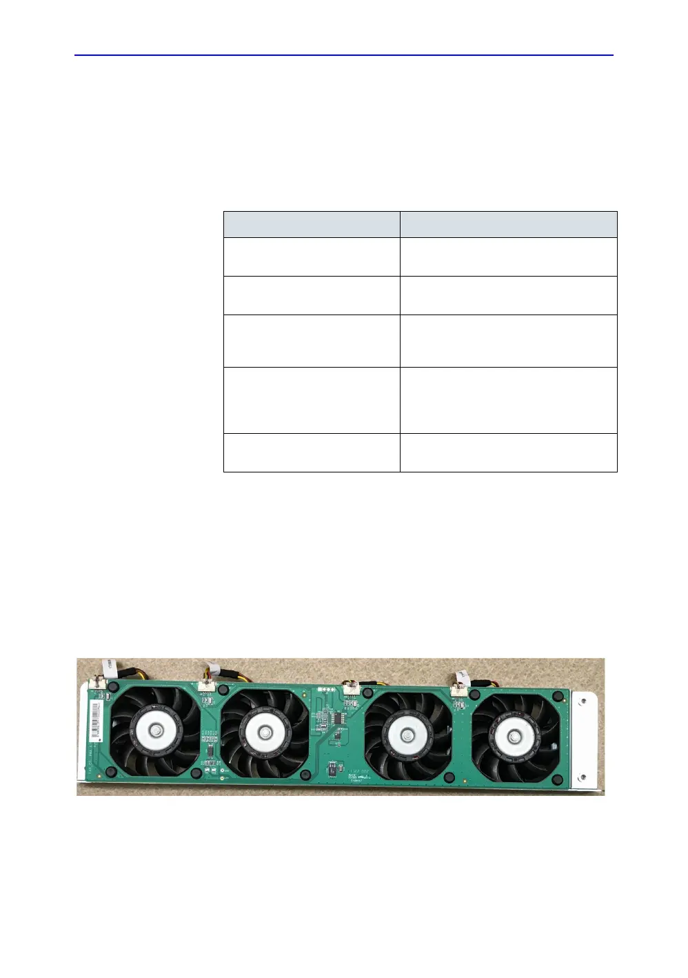
The Ultrasound Box has four fans, as shown in Figure 12. These
pull air up into the box from its bottom; at the chassis top, air is
exhausted under the Service Table. They are mounted on the
Fan Control board in the Ultrasound Box, and commanded by
the cMST board using an I2C interface. The 12 VDC power for
the fan board comes from the MFEPS board.
Figure 5-5. Ultrasound Box fan tray
Table 5-1: Main components in the Ultrasound Box
Component Purpose
cMST board Provides ultrasound 128-channel
processing
MFEPS board Provides power to the cMST board and
the Scan Head and Weight Tower
Motor Control Interface
(daughterboard on the MFEPS
board)
Routes commands from the PC to the
motor control boards in the Scan Head
and Weight Tower
MPSB Relay Board Uses relays to switch signals from the
cMST board to either the Scan Head
transducer or (in future) an auxiliary
transducer.
Ultrasound box fan tray Provides air exhaust from the U/S Box for
cooling

 Loading...