General theory of operation
Invenia ABUS 2.0 – System Setup and Basic Service Manual 5-17
4700-0043-00 Rev. 4
Scan Arm Assembly
Scan Arm main parts
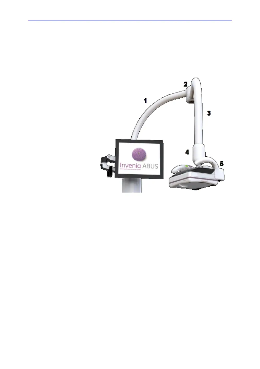
Figure 22 shows the key parts of the Scan Arm.
Figure 5-7. Scan Arm parts
1.Lower tube
2.Hinge assembly
3.Upper tube
4.Ball Joint assembly
5.Scan Head
This assembly is comprised of the lower arm tubing (1) from the
Weight Tower, a hinge (2) at the top, upper arm tube (3), ball
joint mechanism (4) for angular adjustment of Scan Head, and
the Scan Head (5).
The Scan Arm can be slid up or down to position the Scan head,
and rotated by means of the Hinge.
The Ball Joint on the end of the Scan Arm enables the operator
to swivel the Scan Head and at start of a scan, the joint is
electronically commanded to lock position.

 Loading...