Instrument Overview
Invenia ABUS 2.0 – System Setup and Basic Service Manual 1-5
4700-0043-00 Rev. 4
Components
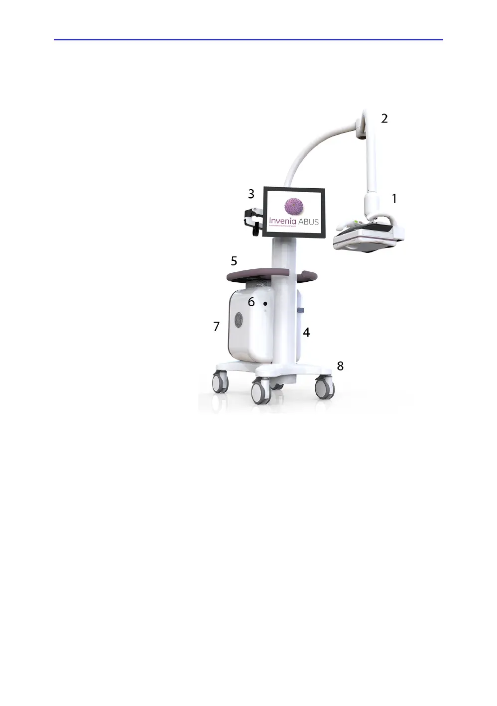
Figure 1-2. Invenia ABUS 2.0 Overview
Signal flows from the transducer in the Scan Head (1), down the
Weight Tower (4), through the Invenia ABUS 2.0 chassis (7),
and finally to the Display (3).
System configuration is stored on the itself. All necessary
software is loaded from the hard drive upon powerup.
1. Scan Head with C15-6XW
Reverse Curve
TM
Ultra-broadband transducer
2. Scan Arm
3. Display Arm with Touch Screen
Monitor
4. Weight Tower
5. Table with Ultrasound Coupling
Lotion Holders
6. System Standby Button (On/Off)
7. Chassis containing Power Cord,
Mains Power Switch, Network
Connector, and USB port (not
shown)
8. Base and
Locking Caster Wheels

 Loading...