DIRECTION 5750007-1EN, REV. 1 LOGIQ E10 BASIC SERVICE MANUAL
Chapter 8 Replacement Procedures 8 - 261
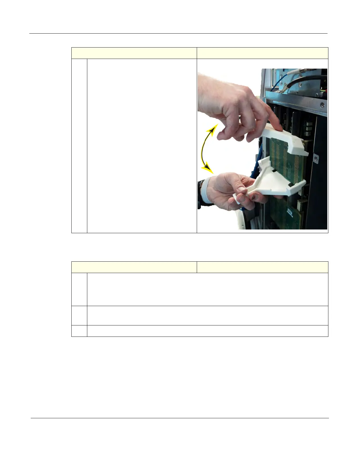
Front Plane Boards installation
1.
Using the Front Plane extraction tools,
place the tools on the Plane to be removed,
as shown. Gently lift on the upper tool and
press down on the lower tool, evenly to pry
the Plane away from the Cards. Maintain
control of the Plane as it frees from the
Cards so it is not dropped.
Place it on an ESD safe place.
Table 8-283 Front Plane Boards installation
Steps Corresponding Graphic
1. Holding the upper and lower edges of the board with both hands, carefully install the Front Plane
Board. Ensure that you do not bend any of the connector pins during the installation.
Apply even pressure across the board and to apply gentle, even pressure at the four corners of
the Front Plane Board to make full contact with the other boards.
2. Install the Card Rack Cover and fasten it with the fixing screws.
Connect the Hi-Pass cable to the GRLY Board and re-install the cover, if present.
3. Re-install all Covers removed.
Table 8-282 Front Plane Boards removal
Step Corresponding Graphic

 Loading...


