Revision B 3-11
Maintenance: Disassembly Guidelines
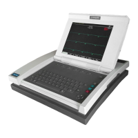
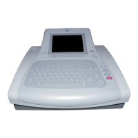
MAC 5000 resting ECG analysis system
2000657-002
Reassembly
1. Slide tabs into their mounting slots and set the display/
keyboard assembly in place.
2. Replace the two TORX mounting screws on the right side of
assembly.
3. Slide the display hinge (metal rod) to the right until it snaps into
the mounting detent.
4. Connect the three cables from the display/keyboard assembly
to the main PCB. Be sure to lift the locks up prior to attempting
to insert the cables into the connectors.
Main PCB
Removal
1. Remove the top cover and display/keyboard assemblies
following the procedures above.
2. Disconnect all remaining cable connections to the main PCB.
These include cables to the
◆ power supply
◆ printhead
◆ battery connect PCB
◆ diskette drive
3. Remove the mounting screws holding the main PCB in place.
They are located around the outside edges of the main PCB.
4. Lift the main PCB from the unit.
Reassembly
1. Reassemble the main PCB reversing the steps for removal.
2. Install the battery and paper, then power on the unit and verify
that the
◆ serial number and printhead resistance (label on printhead)
is correct
◆ setup parameters meet user’s requirements.
Printhead Replacement
Removal
1. Remove the top cover and display/keyboard assemblies
following the procedures above.
2. Using a Phillips head screw driver, remove the two screws that
hold the printhead to the metal roller assembly.
3. Open the writer assembly, disconnect and remove the
printhead.
Reassembly
1. Record the resistance value of the new printhead.
2. Connect the new printhead to the ribbon cable.
3. Hold the new printhead FIRMLY in place against the two metal
tabs on the roller assembly, then tighten the two screws.

 Loading...