Revision B5-6
CPU Theory of Operation: Theory of Operation
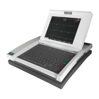
MAC 5000 resting ECG analysis system
2000657-002
Theory of Operation
Clocks
The main system logic operates from one of three clocks, all derived
from a single 24MHz oscillator. That 24MHz clock is used directly by the
FPGA to control the timing of internal peripherals. It is also used as the
reference frequency for the LCD controller PLL clock synthesizer (after
division to 12MHz) and the PLL clock synthesizer in the StrongARM
(after division to 4MHz). In addition, each of the four HC05
microcontrollers has its own 4MHz ceramic resonator.
CPU
The Intel StrongARM SA-110 CPU, chosen for its high performance, low
power consumption and high code density, is at the heart of MAC 5000.
The SA-110 is a bare processor with no integrated peripherals other than
clock generation, MMU and L1 cache. The StrongARM core and bus
clocks are generated internally from an external reference clock. The
multiplying factors for each clock are set by strapping configuration
pins. See theCPU schematic and StrongARM data sheet for the current
CPU and bus speed settings (at the time of this writing, the CPU clock
was 206MHz and the bus clock was 26MHz).
FPGA
All of the MAC 5000’s proprietary hardware is contained in a single
Xilinx FPGA which contains:
■ Bootstrap Instruction Unpacker
■ EDO DRAM Controller
■ XBus Controller
■ LCD Controller VLB Bus Interface
■ Video Waveform Scroller
■ Interrupt Controller
■ System Interrupt Generator
■ Acquisition Module Interface
■ Thermal Printhead Interface
■ Serial EEPROM Interface
■ BBus Interface
■ Two UARTs
■ Four PWMAnalog Outputs
■ Beep Generator
■ Two Serial Ports
The following descriptions give an overview of the FPGA’s functionality.
For detailed information on the internal circuitry, refer to the
schematic.

 Loading...