TERMINAL DESCRIPTION
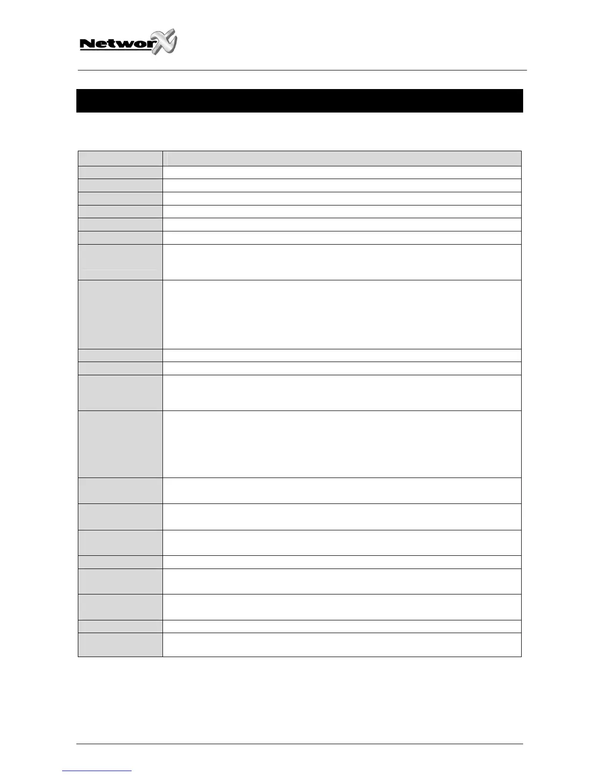
TERMINAL DESCRIPTION
R1 House Telephone Ring.
R Telephone Ring.
T Telephone Tip.
T1 House Telephone Tip.
AC AC input. Connect to a 16.5V 35VA CE approved transformer.
EARTH Earth Ground.
AUX 1
Connect negative lead of low current device [relay, LED (install 1K Ω resistor in series with
LED), etc.]. Connect positive lead of device to KEYPAD +. Current is limited to 250 mA when
output is negative, and 250 µA when output is positive.
SIREN If used as a siren output (default), the speaker rating should be 15 watt at 8 or 16 ohm, or
30/40 watt at 4, 8, or 16 ohms. If voltage output is selected in location 37, this output
becomes voltage output, 12VDC, 1 Amp maximum load.
NOTE: A 3.3KW resistor may be required across the bell terminals when a 12 VDC siren
is used. If no resistor is used, you may experience voltage leakage into the siren, which
will cause these devices to output a small signal.
COM Connect the negative wire of powered devices such as motion and smoke detectors.
SMOKE+ Smoke detector power 12VDC, 250 mA maximum.
AUX 2
Connect negative lead of low current device [relay, LED (install 1K Ω resistor in series with
LED), etc.]. Connect positive lead of device to KEYPAD +. Current is limited to 250 mA when
output is negative, and 250µA when output is positive.
KP DATA Connect to the data terminal on the keypads and the expanders. Maximum wire run is
800 m with 2 mm² wire. The minimum wire sizes at 75, 150, 300 and 600 m are 0.12, 0.33,
0.83 and 1.3 mm² respectively. These numbers are for one keypad at the end of the wire
and a voltage drop of max. 2 Volts. When connecting more than one keypad to the end of
the wire, a higher gauge wire will be required. The maximum number of devices are max.
8 keypads and max 1 expander.
COM
AUX PWR -
Connect to the Common terminal on the keypads, expanders, and other power devices.
POS
AUX PWR +
Connect to the Positive terminal on the keypads, expanders, and other power devices. This
terminal is limited to 1 amp total current.
ZONE 4
Connect to one side of zone 4 loop. Connect the other side to the COM terminal. Open or
short causes alarm.
COM Common (-) terminal for zones 3 & 4.
ZONE 3
Connect to one side of zone 3 loop. Connect the other side to COM terminal. Open or short
causes alarm.
ZONE 2
Connect to one side of zone 2 loop. Connect the other side to the COM terminal. Open or
short causes alarm.
COM Common (-) terminal for zones 1 & 2.
ZONE 1 Connect to one side of zone 1 loop. Connect the other side to COM terminal. Open or short
causes alarm.
NX-4-EUR Installation manual Page 85 02/07/06

 Loading...


