EasyManua.ls Logo

GE PACE Series User Manual

GE PACE Series
176 pages
To Next Page IconTo Next Page
To Previous Page IconTo Previous Page
Page #22 background imageLoading...
Page #22 background image
3 Status System
K0472 Revision A 3 - 4
3.2 Standard event group
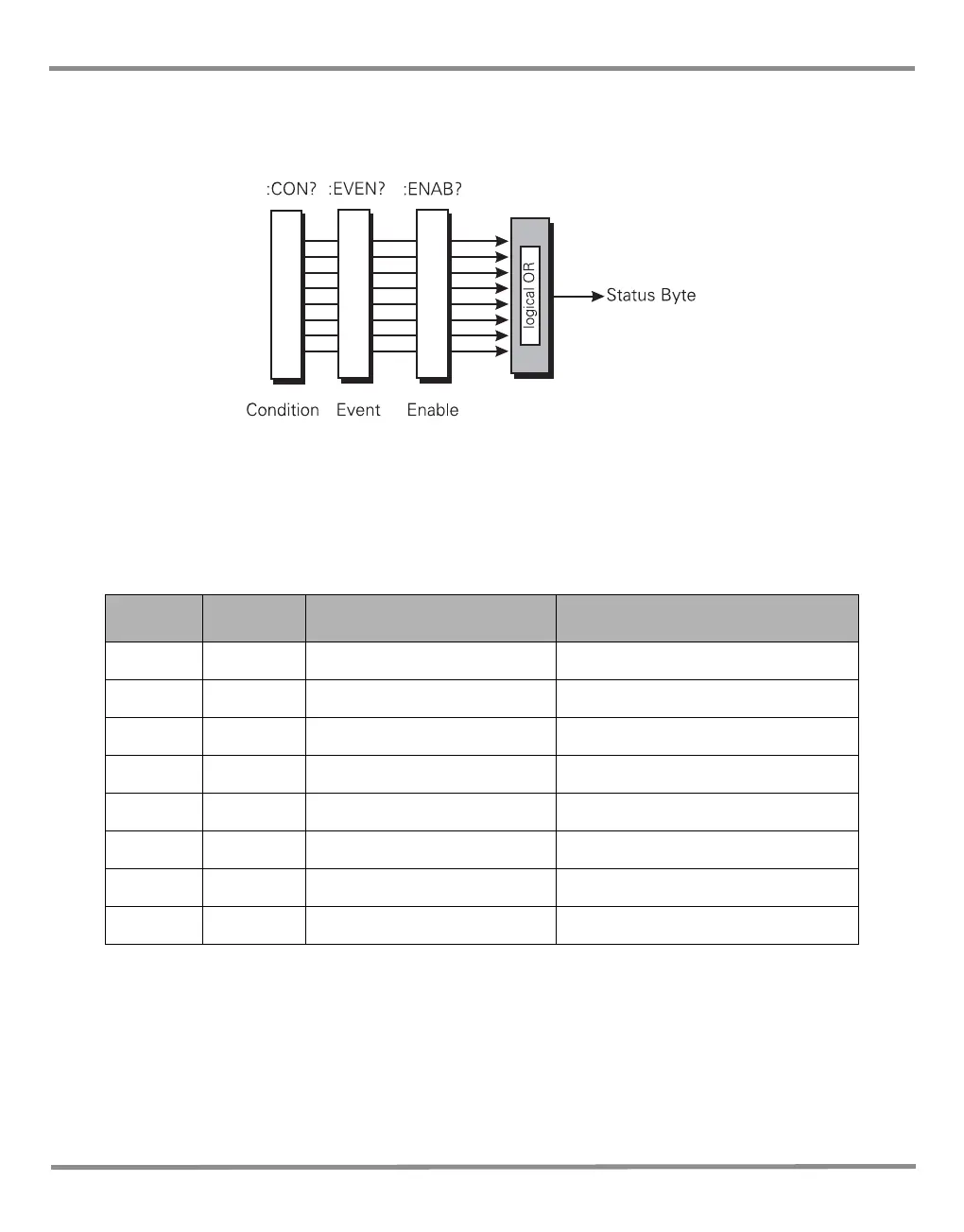
The standard event group are 8 bit registers that are read by the IEEE 488 standard
commands. The event register is cleared by reading it; the event and enable registers are
cleared by the *CLS command.
Bits within the standard event condition register are set by system errors and events. In
addition to setting the status bits, a text message will be placed in the error queue. The ESB
bit in the status byte sets if the associated bit in the event enable register is set. The enable
register may be set through the *ESE command so that selected standard events cause the
ESB bit to be set. The system events that set each bit are as follows:
Table 3-1 Standard Event Register
Bit Name Description Meaning/data
0 OPC Not used Reserved currently returns 0
1 RQC Not used Reserved currently returns 0
2 QYE -400 to -499 Query errors
3 DDE Not used Reserved currently returns 0
4 EXE -200 to -299 Execution errors
5 CME -100 to -199 Command errors
6 URQ Not used Reserved currently returns 0
7 PON Not used Reserved currently returns 0

Table of Contents

Question and Answer IconNeed help?

Do you have a question about the GE PACE Series and is the answer not in the manual?

GE PACE Series Specifications

General IconGeneral
BrandGE
ModelPACE Series
CategoryTest Equipment
LanguageEnglish

Summary

PACE SCPI Manual

Pressure Automated Calibration Equipment

Describes the product line of automated calibration equipment.

SCPI Remote Communications Manual

Manual detailing SCPI protocol for remote control of PACE instruments.

Document Overview

Safety Information

Essential safety instructions for operating the PACE Series equipment.

Technical Advice and Documentation

Guidance on obtaining technical support and related documents.

Abbreviations and Codes

Abbreviations List

Glossary of common abbreviations used throughout the manual.

Code Definitions

Explanations of SCPI command codes and mnemonics.

1 Introduction

General Information

Overview of SCPI protocol and its application to PACE Series instruments.

Remote and Local Operation

Explains how to switch between remote and local control modes.

2 Command Structure

Command Notation and Terminators

Details SCPI command syntax, structure, and message termination rules.

Program Headers

Explains the keywords used to identify commands and queries.

SCPI Data Types

Describes the various data formats used in SCPI communication.

3 Status System

Status Registers Overview

Explains SCPI status reporting and the instrument's register implementation.

Status Reporting Details

Covers output queue, event groups, status bytes, and error handling.

Instrument Errors

Details error codes, messages, and how errors are stored and retrieved.

4 Command and Query Summary

Command Structure and Subsystems

Overview of command organization, subsystems, and command syntax.

Common SCPI Commands

Lists and describes standard SCPI commands prefixed with '*'.

Instrument Control Commands

Lists and describes instrument-specific SCPI commands prefixed with ':'.

5 Errors

Error Codes and Messages

Comprehensive list of SCPI and device-specific error codes and their meanings.

Related product manuals