5-54 T35 Transformer Protection System GE Multilin
5.2 PRODUCT SETUP 5 SETTINGS
5
Each fault report is stored as a file to a maximum capacity of ten files. An eleventh trigger overwrites the oldest file. The
EnerVista UR Setup software is required to view all captured data. A FAULT RPT TRIG event is automatically created when
the report is triggered.
The relay includes two user-programmable fault reports to enable capture of two types of trips (for example, trip from ther-
mal protection with the report configured to include temperatures, and short-circuit trip with the report configured to include
voltages and currents). Both reports feed the same report file queue.
The last record is available as individual data items via communications protocols.
• PRE-FAULT 1 TRIGGER: Specifies the FlexLogic operand to capture the pre-fault data. The rising edge of this oper-
and stores one cycle-old data for subsequent reporting. The element waits for the fault trigger to actually create a
record as long as the operand selected as
PRE-FAULT 1 TRIGGER is “On”. If the operand remains “Off” for 1 second, the
element resets and no record is created.
• FAULT 1 TRIGGER: Specifies the FlexLogic operand to capture the fault data. The rising edge of this operand stores
the data as fault data and results in a new report. The trigger (not the pre-fault trigger) controls the date and time of the
report.
• FAULT REPORT 1 #1 to FAULT REPORT 1 #32: These settings specify an actual value such as voltage or current
magnitude, true RMS, phase angle, frequency, temperature, etc., to be stored should the report be created. Up to 32
channels can be configured. Two reports are configurable to cope with variety of trip conditions and items of interest.
5.2.9 OSCILLOGRAPHY
a) MAIN MENU
PATH: SETTINGS PRODUCT SETUP OSCILLOGRAPHY
Oscillography records contain waveforms captured at the sampling rate as well as other relay data at the point of trigger.
Oscillography records are triggered by a programmable FlexLogic operand. Multiple oscillography records may be captured
simultaneously.
The NUMBER OF RECORDS is selectable, but the number of cycles captured in a single record varies considerably based on
other factors such as sample rate and the number of operational modules. There is a fixed amount of data storage for oscil-
lography; the more data captured, the less the number of cycles captured per record. See the
ACTUAL VALUES
RECORDS OSCILLOGRAPHY menu to view the number of cycles captured per record. The following table provides sam-
ple configurations with corresponding cycles/record. The minimum number of oscillographic records is three.
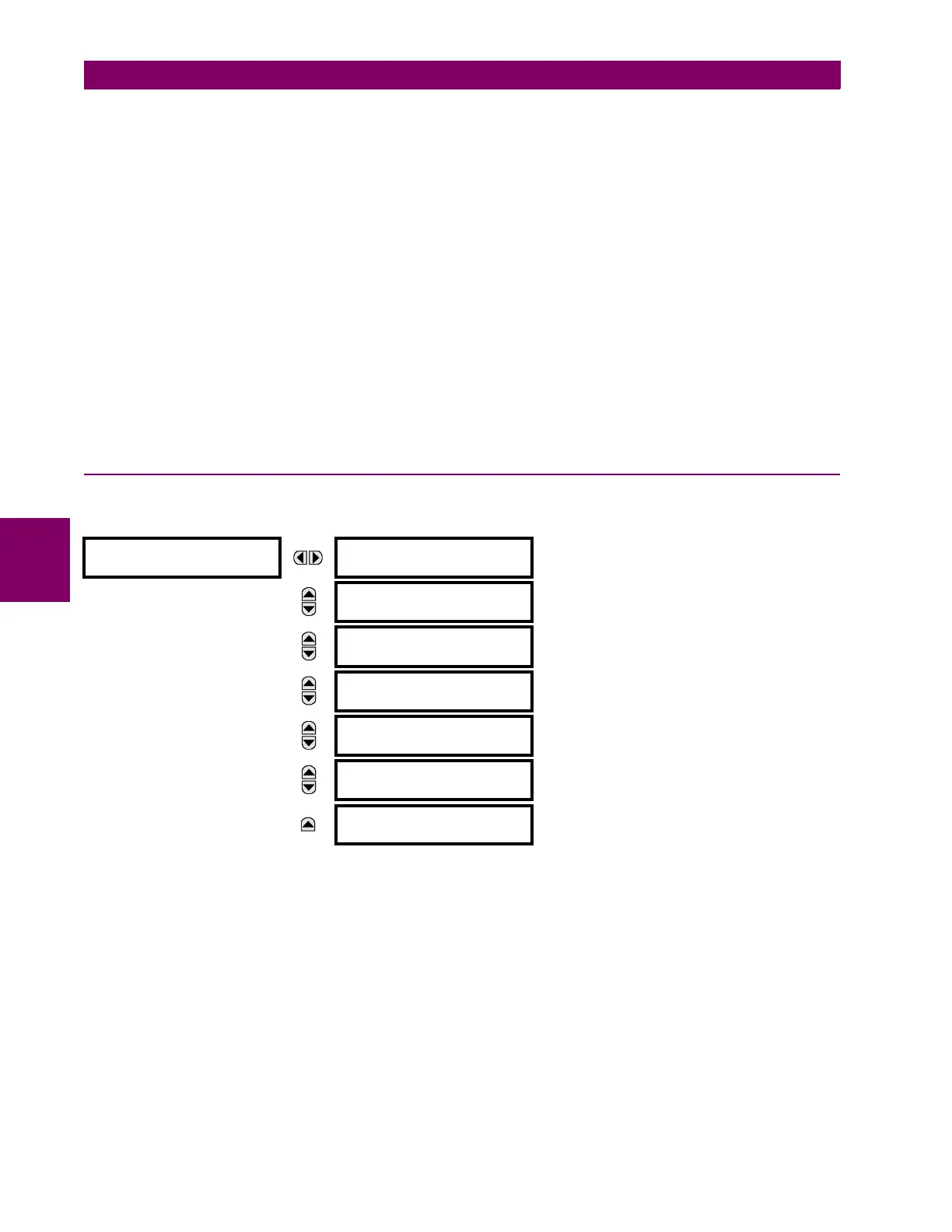
OSCILLOGRAPHY
NUMBER OF RECORDS:
5
Range: 1 to 64 in steps of 1
MESSAGE
TRIGGER MODE:
Automatic Overwrite
Range: Automatic Overwrite, Protected
MESSAGE
TRIGGER POSITION:
50%
Range: 0 to 100% in steps of 1
MESSAGE
TRIGGER SOURCE:
Off
Range: FlexLogic operand
MESSAGE
AC INPUT WAVEFORMS:
16 samples/cycle
Range: Off; 8, 16, 32, 64 samples/cycle
MESSAGE
DIGITAL CHANNELS
MESSAGE
ANALOG CHANNELS

 Loading...


