GE Multilin T35 Transformer Protection System 6-15
6 ACTUAL VALUES 6.3 METERING
6
6.3.3 SOURCES
a) MAIN MENU
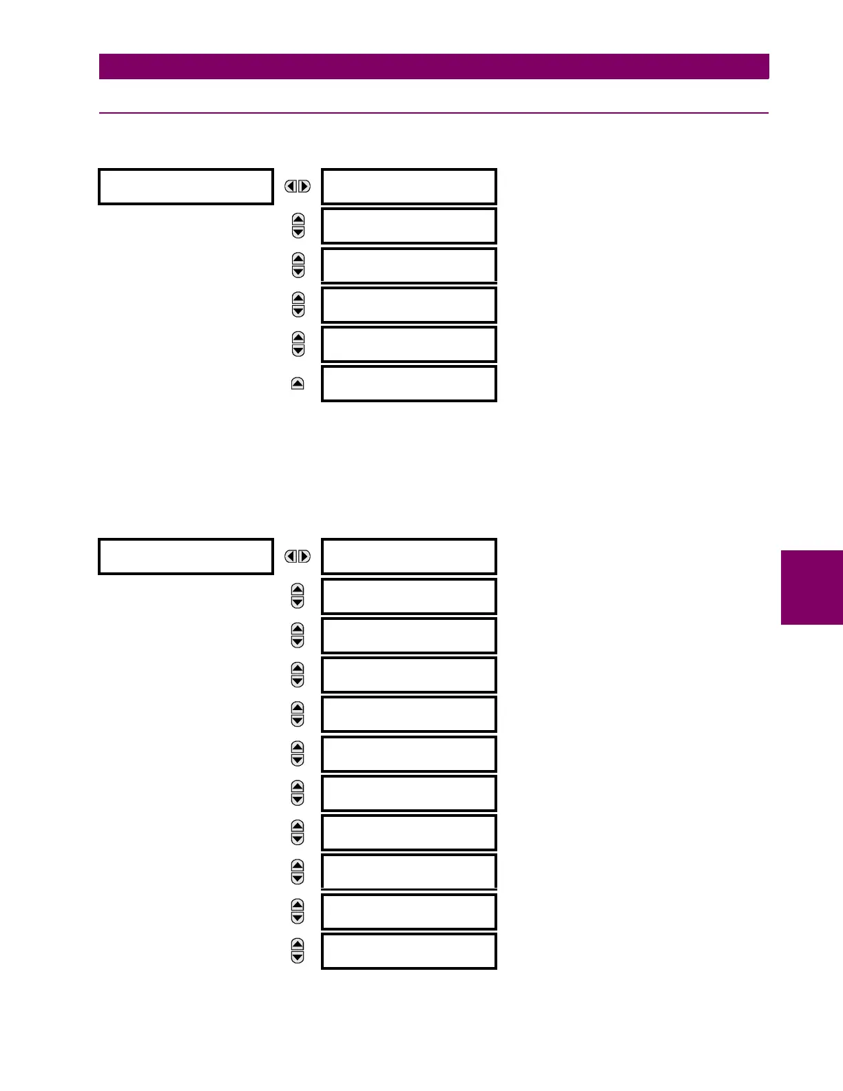
PATH: ACTUAL VALUES METERING SOURCE SRC1
This menu displays the metered values available for each source.
Metered values presented for each source depend on the phase and auxiliary VTs and phase and ground CTs assignments
for this particular source. For example, if no phase VT is assigned to this source, then any voltage, energy, and power val-
ues will be unavailable.
b) PHASE CURRENT METERING
PATH: ACTUAL VALUES METERING SOURCE SRC 1 PHASE CURRENT
SOURCE SRC 1
PHASE CURRENT
SRC 1
See page 6–15.
MESSAGE
GROUND CURRENT
SRC 1
See page 6–16.
MESSAGE
PHASE VOLTAGE
SRC 1
See page 6–16.
MESSAGE
AUXILIARY VOLTAGE
SRC 1
See page 6–17.
MESSAGE
POWER
SRC 1
See page 6–17.
MESSAGE
FREQUENCY
SRC 1
See page 6–18.
PHASE CURRENT
SRC 1
SRC 1 RMS Ia: 0.000
b: 0.000 c: 0.000 A
MESSAGE
SRC 1 RMS Ia:
0.000 A
MESSAGE
SRC 1 RMS Ib:
0.000 A
MESSAGE
SRC 1 RMS Ic:
0.000 A
MESSAGE
SRC 1 RMS In:
0.000 A
MESSAGE
SRC 1 PHASOR Ia:
0.000 A 0.0°
MESSAGE
SRC 1 PHASOR Ib:
0.000 A 0.0°
MESSAGE
SRC 1 PHASOR Ic:
0.000 A 0.0°
MESSAGE
SRC 1 PHASOR In:
0.000 A 0.0°
MESSAGE
SRC 1 ZERO SEQ I0:
0.000 A 0.0°
MESSAGE
SRC 1 POS SEQ I1:
0.000 A 0.0°

 Loading...


