GE Multilin T35 Transformer Protection System 2-13
2 PRODUCT DESCRIPTION 2.2 SPECIFICATIONS
2
2.2.6 POWER SUPPLY
LOW RANGE
Nominal DC voltage: 24 to 48 V
Minimum DC voltage: 20 V
Maximum DC voltage: 60 V
Voltage loss hold-up: 20 ms duration at nominal
NOTE: Low range is DC only.
HIGH RANGE
Nominal DC voltage: 125 to 250 V
Minimum DC voltage: 88 V
Maximum DC voltage: 300 V
Nominal AC voltage: 100 to 240 V at 50/60 Hz
Minimum AC voltage: 88 V at 25 to 100 Hz
Maximum AC voltage: 265 V at 25 to 100 Hz
Voltage loss hold-up: 200 ms duration at nominal
ALL RANGES
Volt withstand: 2 × Highest Nominal Voltage for 10 ms
Power consumption: typical = 15 to 20 W/VA
maximum = 50 W/VA
contact factory for exact order code con-
sumption
INTERNAL FUSE
RATINGS
Low range power supply: 8 A / 250 V
High range power supply: 4 A / 250 V
INTERRUPTING CAPACITY
AC: 100 000 A RMS symmetrical
DC: 10 000 A
2.2.7 OUTPUTS
FORM-A RELAY
Make and carry for 0.2 s: 30 A as per ANSI C37.90
Carry continuous: 6 A
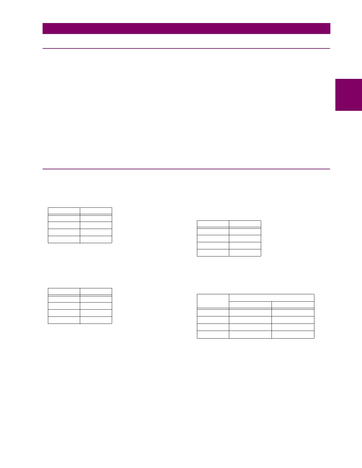
Break (DC inductive, L/R = 40 ms):
Operate time: < 4 ms
Contact material: silver alloy
LATCHING RELAY
Make and carry for 0.2 s: 30 A as per ANSI C37.90
Carry continuous: 6 A as per IEEE C37.90
Break (DC resistive as per IEC61810-1):
Operate time: < 4 ms
Contact material: silver alloy
Control: separate operate and reset inputs
Control mode: operate-dominant or reset-dominant
FORM-A VOLTAGE MONITOR
Applicable voltage: approx. 15 to 250 V DC
Trickle current: approx. 1 to 2.5 mA
FORM-A CURRENT MONITOR
Threshold current: approx. 80 to 100 mA
FORM-C AND CRITICAL FAILURE RELAY
Make and carry for 0.2 s: 30 A as per ANSI C37.90
Carry continuous: 8 A
Break (DC inductive, L/R = 40 ms):
Operate time: < 8 ms
Contact material: silver alloy
FAST FORM-C RELAY
Make and carry: 0.1 A max. (resistive load)
Minimum load impedance:
Operate time: < 0.6 ms
Internal Limiting Resistor: 100 Ω, 2 W
VOLTAGE CURRENT
24 V 1 A
48 V 0.5 A
125 V 0.3 A
250 V 0.2 A
VOLTAGE CURRENT
24 V 6 A
48 V 1.6 A
125 V 0.4 A
250 V 0.2 A
VOLTAGE CURRENT
24 V 1 A
48 V 0.5 A
125 V 0.3 A
250 V 0.2 A
INPUT
VOLTAGE
IMPEDANCE
2 W RESISTOR 1 W RESISTOR
250 V DC 20 KΩ 50 KΩ
120 V DC 5 KΩ 2 KΩ
48 V DC 2 KΩ 2 KΩ
24 V DC 2 KΩ 2 KΩ
Note: values for 24 V and 48 V are the same due to a
required 95% voltage drop across the load impedance.

 Loading...


