9-12 T35 Transformer Protection System GE Multilin
9.3 INRUSH INHIBIT TEST 9 COMMISSIONING
9
9.3INRUSH INHIBIT TEST 9.3.1 INRUSH INHIBIT TEST PROCEDURE
The Inrush Inhibit Test requires a secondary injection test capable of producing a current with an adjustable second
harmonic component. Use the appropriate commissioning tables at the end of this chapter to record values.
This procedure is based upon the example provided in the Differential Characteristic Test Example section. The trans-
former parameters are as follows:
Transformer: Y/y0°, 230/69 kV, CT1 (300:1), CT2 (1000:1)
2nd Harmonic Setting = 20%
1. Connect the relay test set to inject current into the Winding 1 Phase A CT input.
2. Inject currents into the relay as shown in the table below until the biased differential element picks up.
3. Confirm that only the percent differential element has operated.
4. Increase the harmonic content until the element drops out. Record this value as the Inrush Inhibit Level Pickup.
5. Gradually decrease the harmonic content level until the element picks up. Record this value as the Inrush Inhibit
Level Dropout.
6. Switch off the current.
7. Repeat steps 1 through 6 for phases B and C.
8. Repeat steps 1 through 7 for Winding 2 (and Windings 3 and 4 if necessary).
The second harmonic inhibit feature can be verified by setting the
INRUSH INHIBIT MODE setting as follows:
For INRUSH INHIBIT MODE set to "2-out-of-3":
1. Set the
INRUSH INHIBIT FUNCTION to "Trad. 2nd" and the INRUSH INHIBIT LEVEL to "20%".
2. Inject currents into one CT bank (one winding only) until the biased differential operates for all three phases.
3. Apply a second harmonic to Phase A higher than the set threshold and monitor operation of Phases A, B, and C. The
element should stay operated on all three phases.
4. Apply a second harmonic to Phase B with a level less than the set threshold.
5. Increase the second harmonic level in Phase B. When it passes the set threshold, all three phases of differential pro-
tection should drop out.
For
INRUSH INHIBIT MODE set to "Average":
1. Set the
INRUSH INHIBIT FUNCTION to "Trad. 2nd" and the INRUSH INHIBIT LEVEL to "20%".
2. Inject currents into one CT bank (one winding only) until the biased differential operates for all three phases.
3. Apply a second harmonic to Phase A with a level greater than the set threshold and monitor the operation of the Per-
cent Differential element. The element should drop out when the injected second harmonic level becomes three times
larger than the set threshold.
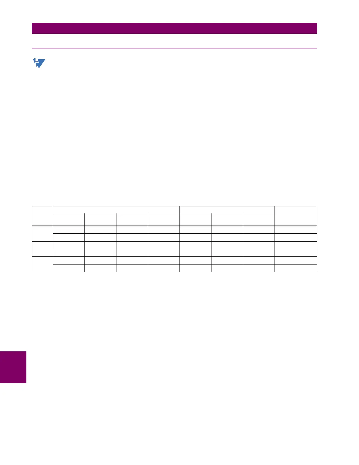
Table 9–1: INRUSH INHIBIT TEST SUMMARY
PHASE INJECTED DISPLAYED STATUS
W1
CURRENT
W1 2ND
HARMONIC
W2
CURRENT
W2 2ND
HARMONIC
I
d
2ND
HARMONIC
I
r
A1 A ∠0° 18.01% 0 A ∠0° 0 0.997 pu 18% 0.997 pu Operate
1 A ∠0° 19.97% 0 A ∠0° 0 0.997 pu 20% 0.997 pu Block
B4 A ∠0° 16.72% 2 A ∠–180° 15% 2 pu 18% 4 pu Operate
4 A ∠0° 17.60% 2 A ∠–180° 15% 2 pu 20% 4 pu Block
C2 A ∠0° 15% 4 A ∠–180° 16.3% 2 pu 18% 4 pu Operate
2 A ∠0° 15% 4 A ∠–180° 17.3% 2 pu 20% 4 pu Block

 Loading...


