6-18 T35 Transformer Protection System GE Multilin
6.3 METERING 6 ACTUAL VALUES
6
The metered values for real, reactive, and apparent power, as well as power factor, are displayed in this menu. The "SRC
1" text is replaced by whatever name was programmed by the user for the associated source (see
SETTINGS SYSTEM
SETUP
SIGNAL SOURCES).
When VTs are configured in wye, the T35 calculates power in each phase and three-phase power is measured as
S = V
A
x Î
A
+ V
B
x Î
B
+ V
C
x Î
C
(EQ 6.1)
When VTs are configured in delta, the T35 does not calculate power in each phase and three-phase power is measured as
S = V
AB
x Î
A
+ V
CB
x Î
C
(EQ 6.2)
where
S is the apparent power
V
A
, V
B
, V
C
, I
A
, I
B
, I
C
are phase voltage and phase current phasors
V
AB
and V
CB
are phase-to-phase voltage phasors
Î is the conjugate of I
g) FREQUENCY METERING
PATH: ACTUAL VALUES METERING SOURCE SRC 1 FREQUENCY
The metered frequency values are displayed in this menu. The "SRC 1" text will be replaced by whatever name was pro-
grammed by the user for the associated source (see
SETTINGS SYSTEM SETUP SIGNAL SOURCES).
SOURCE FREQUENCY is measured via software-implemented zero-crossing detection of an AC signal. The signal is either a
Clarke transformation of three-phase voltages or currents, auxiliary voltage, or ground current as per source configuration
(see the
SYSTEM SETUP POWER SYSTEM settings). The signal used for frequency estimation is low-pass filtered. The
final frequency measurement is passed through a validation filter that eliminates false readings due to signal distortions and
transients.
6.3.4 TRACKING FREQUENCY
PATH: ACTUAL VALUES METERING TRACKING FREQUENCY
The tracking frequency is displayed here. The frequency is tracked based on the selection of the reference source with the
FREQUENCY AND PHASE REFERENCE setting in the SETTINGS SYSTEM SETUP POWER SYSTEM menu. Refer to the
Power System section of chapter 5 for additional details.
6.3.5 FLEXELEMENTS
PATH: ACTUAL VALUES METERING FLEXELEMENTS FLEXELEMENT 1(16)
The operating signals for the FlexElements are displayed in pu values using the following definitions of the base units.
MESSAGE
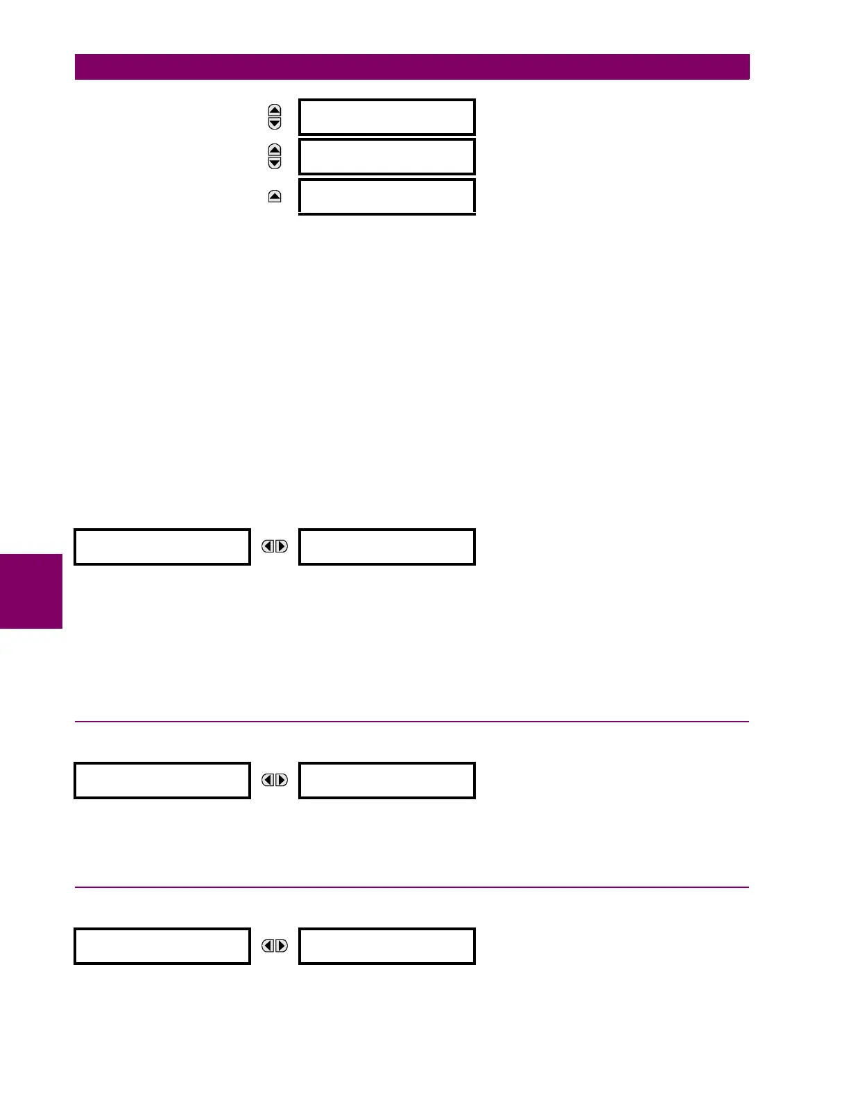
SRC 1 POWER FACTOR
φa: 1.000
MESSAGE
SRC 1 POWER FACTOR
φb: 1.000
MESSAGE
SRC 1 POWER FACTOR
φc: 1.000
FREQUENCY
SRC 1
SRC 1 FREQUENCY:
0.00 Hz
TRACKING FREQUENCY
TRACKING FREQUENCY:
60.00 Hz
FLEXELEMENT 1
FLEXELEMENT 1
OpSig: 0.000 pu

 Loading...


